Data Communication and Networking

This document provides an introduction to data communication and networking. It discusses analog and digital data, data communication, data flow including simplex, half-duplex and full-duplex, and modems. It also covers local area networks, metropolitan area networks, wide area networks, network topologies including linear bus, star, tree and others. Finally, it discusses the OSI model and considerations for data communication networks including performance, consistency, reliability and recovery. Read less

More Related Content
- 1. 1 Introduction to Data Communication & Networking Anjan Mahanta [email protected]
- 2. CopyrightMr.Anjan Mahanta LCCTInternational Studies Program 2 Data & Signals Data can be analog or digital Analog data refers to information that is continuous Analog data take on continuous values Digital data refers to information that has discrete states
- 3. CopyrightMr.Anjan Mahanta LCCTInternational Studies Program 3 Data Communication Data Communications is the transfer of data or information between a source and a receiver. The source transmits the data and the receiver receives it. The purpose of data communications is to provide the rules and regulations that allow computers with different disk operating systems, languages, cabling and locations to share resources. The rules and regulations are called protocols and standards in data communications.
- 4. CopyrightMr.Anjan Mahanta LCCTInternational Studies Program 4 Data Communication
- 5. CopyrightMr.Anjan Mahanta LCCTInternational Studies Program 5 Data Flow Data flow is the flow of data between two points. The direction of the data flow can be described as: 1. Simplex: data flows in only one direction on the data communication line (medium). Examples are radio and television broadcasts.
- 6. CopyrightMr.Anjan Mahanta LCCTInternational Studies Program 6 2. Half-Duplex data flows in both directions but only one direction at a time on the data communication line. For example, a conversation on walkie-talkies is a half-duplex data flow. Each person takes turns talking. If both talk at once - nothing occurs!
- 7. CopyrightMr.Anjan Mahanta LCCTInternational Studies Program 7 3. Full Duplex Data flows in both directions simultaneously. Modems are configured to flow data in both directions. Bi-directional both directions simultaneously!
- 8. CopyrightMr.Anjan Mahanta LCCTInternational Studies Program 8 Modems A modem (MOdulator/DEModulator) is a device that enables a computer to transmit data over, for example, telephone or cable lines. Computer information is stored digitally, whereas information transmitted over telephone lines is transmitted in the form of analog waves.
- 9. CopyrightMr.Anjan Mahanta LCCTInternational Studies Program 9 How fast the modem can transmit and receive data? At slow rates, modems are measured in terms of baud rates The slowest rate is 300 baud At higher speeds, modems are measured in terms of bits per second (bps) The fastest modems run at 57,600 bps The faster the transmission rate, the faster you can send and receive data For example, if the device sending data to your computer is sending it at 2,400 bps, you must receive it at 2,400 bps
- 10. CopyrightMr.Anjan Mahanta LCCTInternational Studies Program 10 About Voice/Data Many modems support a switch to change between voice and data modes In data mode, the modem acts like a regular modem In voice mode, the modem acts like a regular telephone Modems that support a voice/data switch have a built-in loudspeaker and microphone for voice communication
- 11. CopyrightMr.Anjan Mahanta LCCTInternational Studies Program 11 Auto-answer modem An auto-answer modem enables your computer to receive calls in your absence.
- 12. CopyrightMr.Anjan Mahanta LCCTInternational Studies Program 12 Data Compression modem Some modems perform data compression, which enables them to send data at faster rates However, the modem at the receiving end must be able to decompress the data using the same compression technique.
- 13. CopyrightMr.Anjan Mahanta LCCTInternational Studies Program 13 Fax Capability modem Most modern modems are fax modems, which means that they can send and receive faxes.
- 14. CopyrightMr.Anjan Mahanta LCCTInternational Studies Program 14 Digital Connection The connection between the modem and terminal/computer is a digital connection. A basic connection consists of a Transmit Data (TXD) line, a Receive Data (RXD) line and many hardware handshaking control lines. The control lines determine whose turn it is to talk (modem or terminal), if the terminal/computer is turned on, if the modem is turned on, if there is a connection to another modem, etc.
- 15. CopyrightMr.Anjan Mahanta LCCTInternational Studies Program 15 Analog Connection The connection between the modem and the outside world (the phone line) is an analog connection. The voice channel has a bandwidth of 0-4 kHz but only 300 - 3400 Hz is usable for data communications. The modem converts digital information into tones (frequencies) for transmitting through the phone lines. The tones are in the 300-3400 Hz Voice Band.
- 16. CopyrightMr.Anjan Mahanta LCCTInternational Studies Program 16 Types of Modems External Modem – External modems sit next to the computer and connect to the serial port using a straight-through serial cable. Internal Modem – An internal modems is a plug-in circuit board that sits inside the computer. It incorporates the serial port on-board. – They are less expensive than external modems because they do not require a case, power supply and serial cable.
- 17. CopyrightMr.Anjan Mahanta LCCTInternational Studies Program 17 Telecommunications Telephones and networking work hand in hand. The common goal is to join distantly located Local Area Networks into Metropolitan and Wide Area Networks (MANs and WANs). Talking to someone on the phone uses voice channels. We use voice channels for modem communications to connect to the Internet. Due to the bandwidth limits on voice channels, the data transfer rate is relatively slow.
- 18. CopyrightMr.Anjan Mahanta LCCTInternational Studies Program 18 Voice Channels Voice Channel: Dial-up connection through a modem using standard telephone lines. Typical voice channel communication rates are: 300, 1200, 2400, 9600, 14.4k, 19.2k, 28.8k, 33.6k and 56 kbps (bits per second).
- 19. CopyrightMr.Anjan Mahanta LCCTInternational Studies Program 19 Data Channels Data channels are dedicated lines for communicating digitized voice and data. At the end of 1996, there was a major milestone when more data was communicated in North America's telecommunications system than voice. Data Channels are special communications channels provided by "common carriers" such as Telus, Sprint, Bell Canada, AT&T, etc. for transferring digital data. Data Channels are also called "Leased Lines".
- 20. CopyrightMr.Anjan Mahanta LCCTInternational Studies Program 20 Data Channels(Contd.) They are "directly" connected: you don't have to dial a connection number. The connections are up and running 24 hours per day. They appear to work as if there were a wire running directly between the source and the destination. Typical transfer rates for data channels are: 56 k, 128k, 1.544 M, 2.08 M, 45M and 155 Mbps.
- 21. CopyrightMr.Anjan Mahanta LCCTInternational Studies Program 21 Data Channels(Contd.) Common carriers charge for data connections by: –The amount of data transferred (megabytes per month) –The transfer rate (bits per second) –The amount of use (time per month)
- 22. CopyrightMr.Anjan Mahanta LCCTInternational Studies Program 22 What is a network? A network can consist of two computers connected together on a desk or it can consist of many Local Area Networks (LANs) connected together to form a Wide Area Network (WAN) across a continent. The key is that two or more computers are connected together by a medium and are sharing resource. These resources can be files, printers, hard-drives, or CPU number-crunching power.
- 23. CopyrightMr.Anjan Mahanta LCCTInternational Studies Program 23
- 24. CopyrightMr.Anjan Mahanta LCCTInternational Studies Program 24 Breaking the big picture Local loops LANs MANs WANs
- 25. CopyrightMr.Anjan Mahanta LCCTInternational Studies Program 25 Local loops The Local Loop is often called "the last mile" It refers to the last mile of analog phone line that goes from the telephone company's central office (CO) to your house.
- 26. CopyrightMr.Anjan Mahanta LCCTInternational Studies Program 26 Local Area Networks (LANs) LANs (local area networks) are networks that connect computers and resources together in a building or buildings that are close together. The components used by LANs can be divided into cabling standards, hardware, and protocols.
- 27. CopyrightMr.Anjan Mahanta LCCTInternational Studies Program 27 Metropolitan Area Networks(MANs) Metropolitan Area Networks (MANs) are networks that connect LANs together within a city. The main criterion for a MAN is that the connection between LANs is through a local exchange carrier (the local phone company).
- 28. CopyrightMr.Anjan Mahanta LCCTInternational Studies Program 28 Wide Area Networks(WANs) Wide Area Networks (WANs) connect LANs together between cities. The main difference between a MAN and a WAN is that the WAN uses Long Distance Carriers. Otherwise the same protocols and equipment are used as a MAN.
- 29. CopyrightMr.Anjan Mahanta LCCTInternational Studies Program 29 Network Topology What is a Topology? The physical topology of a network refers to the configuration of cables, computers, and other peripherals. Main types of physical topologies 1. Linear Bus 2. Star 3. Star-wired ring 4. Tree
- 30. CopyrightMr.Anjan Mahanta LCCTInternational Studies Program 30 Linear Bus A linear bus topology consists of a main run of cable with a terminator at each end (See figure). All nodes (file server, workstations, and peripherals) are connected to the linear cable. Ethernet and local talk networks use a linear bus topology.
- 31. CopyrightMr.Anjan Mahanta LCCTInternational Studies Program 31 Linear Bus Advantages of linear bus Easy to connect a computer or peripheral to a linear bus. Requires less cable length than a star topology. Disadvantages of linear bus Entire network shuts down if there is a break in the main cable. Terminators are required at both ends of the backbone cable. Difficult to identify the problem if the entire network shuts down. Not meant to be used as a stand-alone solution in a large building.
- 32. CopyrightMr.Anjan Mahanta LCCTInternational Studies Program 32 Star A star topology is designed with each node (file server, workstations, and peripherals) connected directly to a central network hub or concentrator (See figure). Data on a star network passes through the hub or concentrator before continuing to its destination.
- 33. CopyrightMr.Anjan Mahanta LCCTInternational Studies Program 33 Star Advantages of star Easy to install and wire. No disruptions to the network then connecting or removing devices. Easy to detect faults and to remove parts. Disadvantages of star Requires more cable length than a linear topology. If the hub or concentrator fails, nodes attached are disabled. More expensive than linear bus topologies because of the cost of the concentrators.
- 34. CopyrightMr.Anjan Mahanta LCCTInternational Studies Program 34 Star-Wired Ring A star-wired ring topology may appear (externally) to be the same as a star topology. Internally, the MAU (multistation access unit) of a star-wired ring contains wiring that allows information to pass from one device to another in a circle or ring
- 35. CopyrightMr.Anjan Mahanta LCCTInternational Studies Program 35 Tree A tree topology combines characteristics of linear bus and star topologies. It consists of groups of star-configured workstations connected to a linear bus backbone cable Tree topologies allow for the expansion of an existing network, and enable schools to configure a network to meet their needs.
- 36. CopyrightMr.Anjan Mahanta LCCTInternational Studies Program 36 Tree Advantages – Point-to-point wiring for individual segments. – Supported by several hardware and software vendors. Disadvantages – Overall length of each segment is limited by the type of cabling used. – If the backbone line breaks, the entire segment goes down. – More difficult to configure and wire than other topologies.
- 37. CopyrightMr.Anjan Mahanta LCCTInternational Studies Program 37 Considerations When Choosing a Topology: Money. A linear bus network may be the least expensive way to install a network; you do not have to purchase concentrators. Length of cable needed. The linear bus network uses shorter lengths of cable. Future growth. With a star topology, expanding a network is easily done by adding another concentrator. Cable type. The most common cable in schools is unshielded twisted pair, which is most often used with star topologies.
- 38. CopyrightMr.Anjan Mahanta LCCTInternational Studies Program 38 Summary Chart Physical Topology Common Cable Common Protocol Linear Bus Twisted Pair Ethernet coaxial Fiber LocalTalk Star Twisted Pair Ethernet Fiber LocalTalk Star-Wired Ring Twisted Pair Token Ring Tree Twisted Pair Ethernet Coaxial Fiber
- 39. CopyrightMr.Anjan Mahanta LCCTInternational Studies Program 39 Introduction to the ISO - OSI Model The ISO (International Standards Organization) has created a layered model, called the OSI (Open Systems Interconnect) model. The purpose of the layers is to provide clearly defined functions that can improve Internetwork connectivity between "computer" manufacturing companies. Each layer has a standard defined input and a standard defined output.
- 40. CopyrightMr.Anjan Mahanta LCCTInternational Studies Program 40 7 layers of the OSI Model 7. Application Layer (Top Layer) 6. Presentation Layer 5. Session Layer 4. Transport Layer 3. Network Layer 2. Data Link Layer 1. Physical Layer (Bottom Layer)
- 41. CopyrightMr.Anjan Mahanta LCCTInternational Studies Program 41 7 layers of the OSI Model
- 42. CopyrightMr.Anjan Mahanta LCCTInternational Studies Program 42 Information Exchange Process
- 43. CopyrightMr.Anjan Mahanta LCCTInternational Studies Program 43
- 44. CopyrightMr.Anjan Mahanta LCCTInternational Studies Program 44 Data Communication Network The major criteria that a data communication network must meet are: –Performance –Consistency –Reliability –Recovery –Security
- 45. CopyrightMr.Anjan Mahanta LCCTInternational Studies Program 45 Performance Performance is the defined as the rate of transference of error-free data. It is measured by the response time. Response time is the elapsed time between the end of an inquiry and the beginning of a response – Example requesting a file transfer and starting the file transfer. Factors that affect response time are: – Number of Users: – Transmission Speed: – Hardware Type: – Software Program:
- 46. CopyrightMr.Anjan Mahanta LCCTInternational Studies Program 46 Consistency Consistency is the predictability of response time and accuracy of data. – For example, if the "normal" response time is 3 seconds for printing to a network printer but a response time of over 30 seconds occurs, we know that there is a problem in the system!
- 47. CopyrightMr.Anjan Mahanta LCCTInternational Studies Program 47 Reliability Reliability is the measure of how often a network is usable. MTBF (Mean Time Between Failures) is a measure of the average time a component is expected to operate between failures, and is normally provided by the manufacturer. A network failure can be caused by a problem with the hardware, the data carrying medium, or the Network Operating System.
- 48. CopyrightMr.Anjan Mahanta LCCTInternational Studies Program 48 Recovery Recovery is the network's ability to return to a prescribed level of operation after a network failure. This level is where the amount of lost data is nonexistent or at a minimum. Recovery is based on having back-up files.
- 49. CopyrightMr.Anjan Mahanta LCCTInternational Studies Program 49 Security Security is the protection of hardware, software and data from unauthorized access. Restricted physical access to computers, password protection, limiting user privileges and data encryption are common security methods. Anti-virus monitoring programs to defend against computer viruses are also a security measure.
- 50. CopyrightMr.Anjan Mahanta LCCTInternational Studies Program 50 Application Electronic Mail (e-mail or Email) Teleconferencing allows people in different regions to "attend" meetings using telephone lines. Automated Banking Machines allow banking transactions to be performed everywhere Groupware is the latest network application. It allows user groups to share documents, schedules databases, etc. (ex. Lotus Notes)
- 51. CopyrightMr.Anjan Mahanta LCCTInternational Studies Program 51 Physical Connection The physical connection determines how many bits (1's or 0's) can be transmitted in a single instance of time. If only 1 bit of information can be transmitted over the data transmission medium at a time then it is considered a serial communication. If more than 1 bit of information is transmitted over the data transmission medium at a time then it is considered a parallel communication.
- 52. CopyrightMr.Anjan Mahanta LCCTInternational Studies Program 52
- 53. CopyrightMr.Anjan Mahanta LCCTInternational Studies Program 53 Communications Advantages Parallel : faster transfer rates Serial : long distances Disadvantages Parallel: short distance only Serial : slow transfer rates
- 54. CopyrightMr.Anjan Mahanta LCCTInternational Studies Program 54 Transmission Media- Guided There are 2 basic categories of transmission media: guided and unguided. Guided transmission media uses a cabling system that guides the data signals along a specific path. Unguided transmission media consists of a means for the data signals to travel but nothing to guide them along a specific path.
- 55. CopyrightMr.Anjan Mahanta LCCTInternational Studies Program 55 Transmission Media- Guided There 4 basic types of guided media: Open Wire Twisted Pair Coaxial Cable Optical Fiber
- 56. CopyrightMr.Anjan Mahanta LCCTInternational Studies Program 56 Open wire Open wire is traditionally used to describe the electrical wire strung along power poles. There is a single wire strung between poles. No shielding or protection from noise interference is used.
- 57. CopyrightMr.Anjan Mahanta LCCTInternational Studies Program 57 Twisted Pair The wires in twisted pair cabling are twisted together in pairs. Each pair consists of a wire used for the +ve data signal and a wire used for the -ve data signal. Any noise that appears on 1 wire of the pair will also occur on the other wire. When the noise appears on both wires, it cancels or nulls itself out at the receiving end.
- 58. CopyrightMr.Anjan Mahanta LCCTInternational Studies Program 58 Unshielded Twisted Pair The degree of reduction in noise interference is determined specifically by the number of turns per foot. Increasing the number of turns per foot reduces the noise interference. To further improve noise rejection, a foil or wire braid "shield" is woven around the twisted pairs. Cables with a shield are called shielded twisted pair and are commonly abbreviated STP. Cables without a shield are called unshielded twisted pair or UTP.
- 59. CopyrightMr.Anjan Mahanta LCCTInternational Studies Program 59 Coaxial cable Coaxial cable consists of two conductors. The inner conductor is held inside an insulator with the other conductor woven around it providing a shield. An insulating protective coating called a jacket covers the outer conductor.
- 60. CopyrightMr.Anjan Mahanta LCCTInternational Studies Program 60 Coaxial cable The outer shield protects the inner conductor from outside electrical signals. The distance between the outer conductor (shield) and inner conductor plus the type of material used for insulating the inner conductor determine the cable properties or impedance. Typical impedances for coaxial cables are 75 ohms for Cable TV, 50 ohms for Ethernet Thinnet and Thicknet.
- 61. CopyrightMr.Anjan Mahanta LCCTInternational Studies Program 61 Optical fiber Optical fiber consists of thin glass fibers that can carry information at frequencies in the visible light spectrum and beyond. The typical optical fiber consists of a very narrow strand of glass called the core. Around the core is a concentric layer of glass called the cladding. Coating the cladding is a protective coating consisting of plastic, it is called the Jacket.
- 62. CopyrightMr.Anjan Mahanta LCCTInternational Studies Program 62 Optical fiber An important characteristic of fiber optics is refraction. Refraction is the characteristic of a material to either pass or reflect light. When light passes through a medium, it "bends" as it passes from one medium to the other. An example of this is when we look into a pond of water.
- 63. CopyrightMr.Anjan Mahanta LCCTInternational Studies Program 63 Optical fiber If the angle of incidence is small, the light rays are reflected and do not pass into the water. If the angle of incident is great, light passes through the media but is bent or refracted.
- 64. CopyrightMr.Anjan Mahanta LCCTInternational Studies Program 64 Advantages of Optical fiber Noise immunity: RFI and EMI immune (RFI - Radio Frequency Interference, EMI -Electromagnetic Interference) Security: cannot tap into cable. Large Capacity due to BW (bandwidth) No corrosion (destroy metal) Longer distances than copper wire Smaller and lighter than copper wire Faster transmission rate
- 65. CopyrightMr.Anjan Mahanta LCCTInternational Studies Program 65 Disadvantages of Optical fiber Physical vibration will show up as signal noise! Limited physical arc of cable. Bend it too much and it will break! Difficult to splice (to join)
- 66. CopyrightMr.Anjan Mahanta LCCTInternational Studies Program 66 Comparison The following compares the usable bandwidth of the different guided transmission media. Cable Type Bandwidth Open Cable 0 - 5 MHz Twisted Pair 0 - 100 MHz Coaxial Cable 0 - 600 MHz Optical Fiber 0 - 1 GHz
- 67. CopyrightMr.Anjan Mahanta LCCTInternational Studies Program 67 Transmission Media - Unguided Unguided transmission media is data signals that flow through the air. They are not guided or bound to a channel to follow. They are classified by the type of wave propagation. – RF (Radio Frequency) Propagation – Microwave Propagation – Satellite Propagation
- 68. CopyrightMr.Anjan Mahanta LCCTInternational Studies Program 68 RF Propagation There are three types of RF (radio frequency) propagation: 1.Ground Wave 2.Ionospheric 3.Line of Sight (LOS)
- 69. CopyrightMr.Anjan Mahanta LCCTInternational Studies Program 69 Groundwave propagation Ground wave propagation follows the curvature of the Earth. Ground waves have carrier frequencies up to 2 MHz. AM Radio is an example of ground wave propagation.
- 70. CopyrightMr.Anjan Mahanta LCCTInternational Studies Program 70 Ionospheric propagation Ionospheric propagation bounces off of the Earth's ionospheric layer in the upper atmosphere. It operates in the frequency range of 30 - 85 MHz. Because it depends on the Earth's ionosphere, it changes with the weather and time of day. Ham radios operate in this range.
- 71. CopyrightMr.Anjan Mahanta LCCTInternational Studies Program 71 Line of sight propagation Line of sight propagation transmits exactly in the line of sight. The receive station must be in the view of the transmit station. It is limited by the curvature of the Earth for ground-based stations (100 km, from horizon to horizon). Examples of line of sight propagation are: FM radio, microwave and satellite.
- 72. CopyrightMr.Anjan Mahanta LCCTInternational Studies Program 72 Microwave Microwave transmission is line of sight transmission. The transmit station must be in visible contact with the receive station. Typically the line of sight due to the Earth's curvature is only 50 km to the horizon! Repeater stations must be placed so the data signal can hop, skip and jump across the country.
- 73. CopyrightMr.Anjan Mahanta LCCTInternational Studies Program 73 Microwave Microwaves operate at high operating frequencies of 3 to 10 GHz. This allows them to carry large quantities of data due to their large bandwidth. Advantages: – They can carry high quantities of information due to their high operating frequencies. – Low cost land purchase: each tower occupies only a small area. – High frequency/short wavelength signals require small antennae.
- 74. CopyrightMr.Anjan Mahanta LCCTInternational Studies Program 74 Microwave Disadvantages – Attenuation by solid objects: birds, rain, snow and fog. – Reflected from flat surfaces like water and metal. – Diffracted (split) around solid objects. – Refracted by atmosphere, thus causing beam to be projected away from receiver.
- 75. CopyrightMr.Anjan Mahanta LCCTInternational Studies Program 75 Satellite Satellites are transponders (units that receive on one frequency and retransmit on another) that are set in geostationary orbits directly over the equator.
- 76. CopyrightMr.Anjan Mahanta LCCTInternational Studies Program 76 Satellite These geostationary orbits are 36,000 km from the Earth's surface. At this point, the gravitational pull of the Earth and the centrifugal force of Earth's rotation are balanced and cancel each other out.
- 77. CopyrightMr.Anjan Mahanta LCCTInternational Studies Program 77 Satellite The uplink is the transmitter of data to the satellite. The downlink is the receiver of data. Uplinks and downlinks are also called Earth stations because they are located on the Earth. The footprint is the "shadow" that the satellite can transmit to, the shadow being the area that can receive the satellite's transmitted signal.
- 78. CopyrightMr.Anjan Mahanta LCCTInternational Studies Program 78 Networking Devices Repeaters:Repeaters are physical hardware devices: they have a primary function to regenerate the electrical signal The purpose of a repeater is to extend the LAN Segment beyond its physical limits Typically, repeaters are used to connect two physically close buildings together (when they are too far apart to just extend the segment). They can be used to connect floors of a building that would normally surpass the maximum allowable segment length. For large extensions two Repeaters are required but for shorter extensions, only one Repeater may be required.
- 79. CopyrightMr.Anjan Mahanta LCCTInternational Studies Program 79 Networking Devices Repeaters:
- 80. CopyrightMr.Anjan Mahanta LCCTInternational Studies Program 80 Networking Devices Repeaters operate at the OSI Model
- 81. CopyrightMr.Anjan Mahanta LCCTInternational Studies Program 81 Networking Devices Multiport Repeaters
- 82. CopyrightMr.Anjan Mahanta LCCTInternational Studies Program 82 Networking Devices Hubs:Hubs are used to provide a Physical Star Topology. At the center of the star is the Hub, with the network nodes located on the tips of the star. The Hub is installed in a central wiring closet, with all the cables extending out to the network nodes.
- 83. CopyrightMr.Anjan Mahanta LCCTInternational Studies Program 83 Networking Devices Hubs:
- 84. CopyrightMr.Anjan Mahanta LCCTInternational Studies Program 84 Networking Devices Bridges: Bridges are both hardware and software devices.
- 85. CopyrightMr.Anjan Mahanta LCCTInternational Studies Program 85 Networking Devices Purpose of a Bridge The purposes of a Bridge are the following: – Isolates networks by MAC addresses – Manages network traffic by filtering packets – Translates from one protocol to another
- 86. CopyrightMr.Anjan Mahanta LCCTInternational Studies Program 86 Networking Devices Isolates networks by MAC addresses
- 87. CopyrightMr.Anjan Mahanta LCCTInternational Studies Program 87 Networking Devices Manages network traffic by filtering packets Bridges listen to the network traffic, and build an image of the network on each side of the bridge. This image of the network indicates the location of each node With this information, a bridge can make a decision whether to forward the packet across the bridge This process of deciding whether or not to forward a packet is termed "filtering packets."
- 88. CopyrightMr.Anjan Mahanta LCCTInternational Studies Program 88 Networking Devices Translates from one protocol to another Bridges are store and forward devices. They receive a packet on the local segment, store it, and wait for the remote segments to be clear before forwarding the packet.
- 89. CopyrightMr.Anjan Mahanta LCCTInternational Studies Program 89 Networking Devices Reasons to use a Bridge Bandwidth: Reduce traffic by segmentation Reliability: If 1 segment goes down, it does not take down the complete LAN Translation: Translate different Data Link protocols
- 90. CopyrightMr.Anjan Mahanta LCCTInternational Studies Program 90 Networking Devices Gateways A Gateway is the Hardware/Software device that is used to interconnect LANs & WANs using mainframe computers Example: DECnet and IBM's SNA Often, the router that is used to connect a LAN to the Internet will be called a gateway. It will have added capability to direct and filter higher layer protocols (layer 4 and up) to specific devices (such as web servers, ftp servers and e-mail servers).
- 91. CopyrightMr.Anjan Mahanta LCCTInternational Studies Program 91 Protocol IEEE-802.3 The IEEE-802.3 Protocol is based on the Xerox Network Standard (XNS) called Ethernet These are the four versions of the Ethernet frame – Ethernet_802.2 – Ethernet_802.3 – Ethernet_II – Ethernet_SNAP NOTE: The Source and Destination must have the same Ethernet Frame type in order to communicate.
- 92. CopyrightMr.Anjan Mahanta LCCTInternational Studies Program 92 Protocol IEEE-802.3 IEEE 802.3 defines five media types of IEEE 802.3 Ethernet Types shown below: 1. IEEE 802.3 - 10Base5 (Thick Coax) is used only as backbones to networks. Backbones are lines that connect buildings & network equipment together (such as Bridges, Routers, Hubs, Concentrators, Gateways, etc.). 10Base5 is now being replaced by either Thin Coax or fiber optics.
- 93. CopyrightMr.Anjan Mahanta LCCTInternational Studies Program 93 Protocol IEEE-802.3 2.IEEE 802.3a - 10Base2 is commonly used in new installations as a backbone to connect buildings and network equipment together. 10Base2 (Thin Coax) is also used to connect work stations together, but the preferred choice is to use 10BaseT. 3. IEEE 802.3b - 10Broad36 is rarely used; it combines analog and digital signals together. Broadband means that a mixture of signals can be sent on the same medium.
- 94. CopyrightMr.Anjan Mahanta LCCTInternational Studies Program 94 Protocol IEEE-802.3 4. IEEE 802.3e - 1 Base 5 StarLAN is a slow 1 Mbps standard that has been replaced by Thin Coax or Twisted Pair. 5. IEEE 802.3i - 10BaseT is commonly used to connect workstations to network hubs. The network hubs can use 10BaseT (Twisted Pair) to connect to other Hubs.
- 95. CopyrightMr.Anjan Mahanta LCCTInternational Studies Program 95 10 Base T (Twisted Pair Cable) 10BaseT uses unshielded twisted pair (UTP) cable. The cable is flexible and easy to work with. The cable has a characteristic impedance of 100 ohms. There are 2 pairs of twisted wires used with 10BaseT: separate Rx (receive) and Tx (transmit) pairs. The lines are balanced lines to minimize noise and there are a Rx+ & Rx- pair and a Tx+ & Tx- pair.
- 96. CopyrightMr.Anjan Mahanta LCCTInternational Studies Program 96 10 Base T (Twisted Pair Cable) The nodes are connected to a MPR (multi port repeater), also called a Concentrator, or Hub. Maximum Nodes For 10BaseT, the maximum allowed number of nodes is 128 (on one segment). Maximum Distance between Nodes & Hub The maximum distance between nodes & Hub is 100 m.
- 97. CopyrightMr.Anjan Mahanta LCCTInternational Studies Program 97 Cable Termination and Connector The standard termination is 100 ohms. The end connector is an "RJ45" quick disconnect connector. The cable is internally terminated at the NIC (Network Interface Card) and Hub.
- 98. CopyrightMr.Anjan Mahanta LCCTInternational Studies Program 98 TCP/IP Protocols
- 99. CopyrightMr.Anjan Mahanta LCCTInternational Studies Program 99 TCP/IP Protocols Network Devices are network interface cards (NIC) and their software drivers. Typically, they are Ethernet cards, Token Ring cards, and WAN links (such as ISDN or Frame Relay), and they can also be modems and serial ports. IP stands for Internet Protocol. Its main job is to find the best route--through the Internet--to the destination. IP uses IP addresses to identify the host machine and the network.
- 100. CopyrightMr.Anjan Mahanta LCCTInternational Studies Program 100 TCP/IP Protocols A typical IP address is a 32 bit number, and looks like 142.110.237.1. In this case, 142.110.237.0 identifies the network address, and 0.0.0.1 identifies the host machine. ARP stands for Address Resolution Protocol and it is used to map IP addresses to MAC addresses. ICMP stands for Internet Control Message Protocol, and is used mainly for troubleshooting TCP/IP network connections.
- 101. CopyrightMr.Anjan Mahanta LCCTInternational Studies Program 101 TCP/IP Protocols TCP stands for Transmission Control Protocol, and is used to guarantee end to end delivery of segments of data. TCP is used to put out of order segments in order, and to check for transmission errors. UDP stands for User Datagram Protocol, and is a connectionless service. This results in a low overhead and fast transfer service (relies on the upper layer protocols to provide error checking and delivery of data).
- 102. CopyrightMr.Anjan Mahanta LCCTInternational Studies Program 102 In the Application layer lies many hundreds of network- aware programs and services such as the following: HTTP (80) - Hyper Text Transport Protocol, which is used for transferring web pages. SNMP (161/162)- Simple Network Management Protocol, which is used for managing network devices. FTP (20/21)- File Transfer Protocol, which is used for transferring files across the network. TFTP (69)- Trivial File Transfer Protocol, which is a low overhead fast transfer FTP protocol. SMTP (25)- Simple Mail Tranfer Protocol, which is used for transferring email across the Internet. Telnet (23)- An application for remotely logging into a server across the network. NNTP (119)- Network News Transfer Protocol, which is used for transferring news. * The numbers, shown in brackets next to the protocols, are called the well-known Port Numbers.
- 103. CopyrightMr.Anjan Mahanta LCCTInternational Studies Program 103 Wireless Network What is wireless networking? A wireless network is simply two or more computers (and maybe printers) linked by radio waves. There are various other devices that can connect to this wireless network. This arrangement uses a protocol (method of communication) called, IEEE 802.11b, or Wi-Fi
- 104. CopyrightMr.Anjan Mahanta LCCTInternational Studies Program 104 Range & Performance Wi-Fi is currently the fastest wireless technology. It can transmit through walls and floors at speeds of up to 11 Mbps. Bandwidths available:- 11Mbps 22Mbps 54Mbps Super G 108Mbps
- 105. CopyrightMr.Anjan Mahanta LCCTInternational Studies Program 105 Wireless adapters Wireless network adapters can be internal (inserted in a computer) or external (housed in a separate case). The two general types of wireless adapters are: USB adapter: Connects through a USB cable to a USB port on your desktop computer. USB adapters are popular because they are easy to install and to swap between desktop computers as necessary. Notebook adapter: Fits into the PCMCIA slot on your laptop or other portable computer. Notebook adapters eliminate the need for cable connections to the computer and are popular among users who value mobility.
- 106. CopyrightMr.Anjan Mahanta LCCTInternational Studies Program 106 Benefits of wireless network Convenience: You can set up wireless connections without having to run cables or open computer cases. Mobility: Mobility might be relatively unimportant for a desktop computer but can be an important benefit if you have a laptop or notebook computer.
- 107. CopyrightMr.Anjan Mahanta LCCTInternational Studies Program 107 Bandwidth Case I bandwidth in bits per second, refersto the speed of bit transmission in a channel or link
- 108. CopyrightMr.Anjan Mahanta LCCTInternational Studies Program 108 Bandwidth Case II
We use essential cookies to make Venngage work. By clicking “Accept All Cookies”, you agree to the storing of cookies on your device to enhance site navigation, analyze site usage, and assist in our marketing efforts.
Manage Cookies
Cookies and similar technologies collect certain information about how you’re using our website. Some of them are essential, and without them you wouldn’t be able to use Venngage. But others are optional, and you get to choose whether we use them or not.
Strictly Necessary Cookies
These cookies are always on, as they’re essential for making Venngage work, and making it safe. Without these cookies, services you’ve asked for can’t be provided.
Show cookie providers
- Google Login
Functionality Cookies
These cookies help us provide enhanced functionality and personalisation, and remember your settings. They may be set by us or by third party providers.
Performance Cookies
These cookies help us analyze how many people are using Venngage, where they come from and how they're using it. If you opt out of these cookies, we can’t get feedback to make Venngage better for you and all our users.
- Google Analytics
Targeting Cookies
These cookies are set by our advertising partners to track your activity and show you relevant Venngage ads on other sites as you browse the internet.
- Google Tag Manager
- Infographics
- Daily Infographics
- Popular Templates
- Accessibility
- Graphic Design
- Graphs and Charts
- Data Visualization
- Human Resources
- Beginner Guides
Blog Data Visualization 10 Data Presentation Examples For Strategic Communication
10 Data Presentation Examples For Strategic Communication
Written by: Krystle Wong Sep 28, 2023
Knowing how to present data is like having a superpower.
Data presentation today is no longer just about numbers on a screen; it’s storytelling with a purpose. It’s about captivating your audience, making complex stuff look simple and inspiring action.
To help turn your data into stories that stick, influence decisions and make an impact, check out Venngage’s free chart maker or follow me on a tour into the world of data storytelling along with data presentation templates that work across different fields, from business boardrooms to the classroom and beyond. Keep scrolling to learn more!
Click to jump ahead:
10 Essential data presentation examples + methods you should know
What should be included in a data presentation, what are some common mistakes to avoid when presenting data, faqs on data presentation examples, transform your message with impactful data storytelling.
Data presentation is a vital skill in today’s information-driven world. Whether you’re in business, academia, or simply want to convey information effectively, knowing the different ways of presenting data is crucial. For impactful data storytelling, consider these essential data presentation methods:
1. Bar graph
Ideal for comparing data across categories or showing trends over time.
Bar graphs, also known as bar charts are workhorses of data presentation. They’re like the Swiss Army knives of visualization methods because they can be used to compare data in different categories or display data changes over time.
In a bar chart, categories are displayed on the x-axis and the corresponding values are represented by the height of the bars on the y-axis.
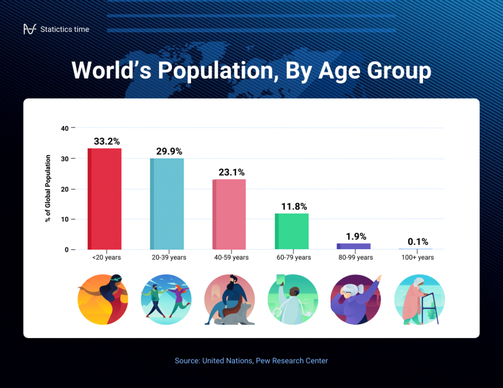
It’s a straightforward and effective way to showcase raw data, making it a staple in business reports, academic presentations and beyond.
Make sure your bar charts are concise with easy-to-read labels. Whether your bars go up or sideways, keep it simple by not overloading with too many categories.

2. Line graph
Great for displaying trends and variations in data points over time or continuous variables.
Line charts or line graphs are your go-to when you want to visualize trends and variations in data sets over time.
One of the best quantitative data presentation examples, they work exceptionally well for showing continuous data, such as sales projections over the last couple of years or supply and demand fluctuations.
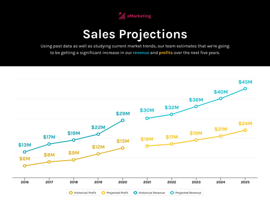
The x-axis represents time or a continuous variable and the y-axis represents the data values. By connecting the data points with lines, you can easily spot trends and fluctuations.
A tip when presenting data with line charts is to minimize the lines and not make it too crowded. Highlight the big changes, put on some labels and give it a catchy title.

3. Pie chart
Useful for illustrating parts of a whole, such as percentages or proportions.
Pie charts are perfect for showing how a whole is divided into parts. They’re commonly used to represent percentages or proportions and are great for presenting survey results that involve demographic data.
Each “slice” of the pie represents a portion of the whole and the size of each slice corresponds to its share of the total.

While pie charts are handy for illustrating simple distributions, they can become confusing when dealing with too many categories or when the differences in proportions are subtle.
Don’t get too carried away with slices — label those slices with percentages or values so people know what’s what and consider using a legend for more categories.

4. Scatter plot
Effective for showing the relationship between two variables and identifying correlations.
Scatter plots are all about exploring relationships between two variables. They’re great for uncovering correlations, trends or patterns in data.
In a scatter plot, every data point appears as a dot on the chart, with one variable marked on the horizontal x-axis and the other on the vertical y-axis.

By examining the scatter of points from heat map software , you can discern the nature of the relationship between the variables, whether it’s positive, negative or no correlation at all.
If you’re using scatter plots to reveal relationships between two variables, be sure to add trendlines or regression analysis when appropriate to clarify patterns. Label data points selectively or provide tooltips for detailed information.

5. Histogram
Best for visualizing the distribution and frequency of a single variable.
Histograms are your choice when you want to understand the distribution and frequency of a single variable.
They divide the data into “bins” or intervals and the height of each bar represents the frequency or count of data points falling into that interval.

Histograms are excellent for helping to identify trends in data distributions, such as peaks, gaps or skewness.
Here’s something to take note of — ensure that your histogram bins are appropriately sized to capture meaningful data patterns. Using clear axis labels and titles can also help explain the distribution of the data effectively.

6. Stacked bar chart
Useful for showing how different components contribute to a whole over multiple categories.
Stacked bar charts are a handy choice when you want to illustrate how different components contribute to a whole across multiple categories.
Each bar represents a category and the bars are divided into segments to show the contribution of various components within each category.
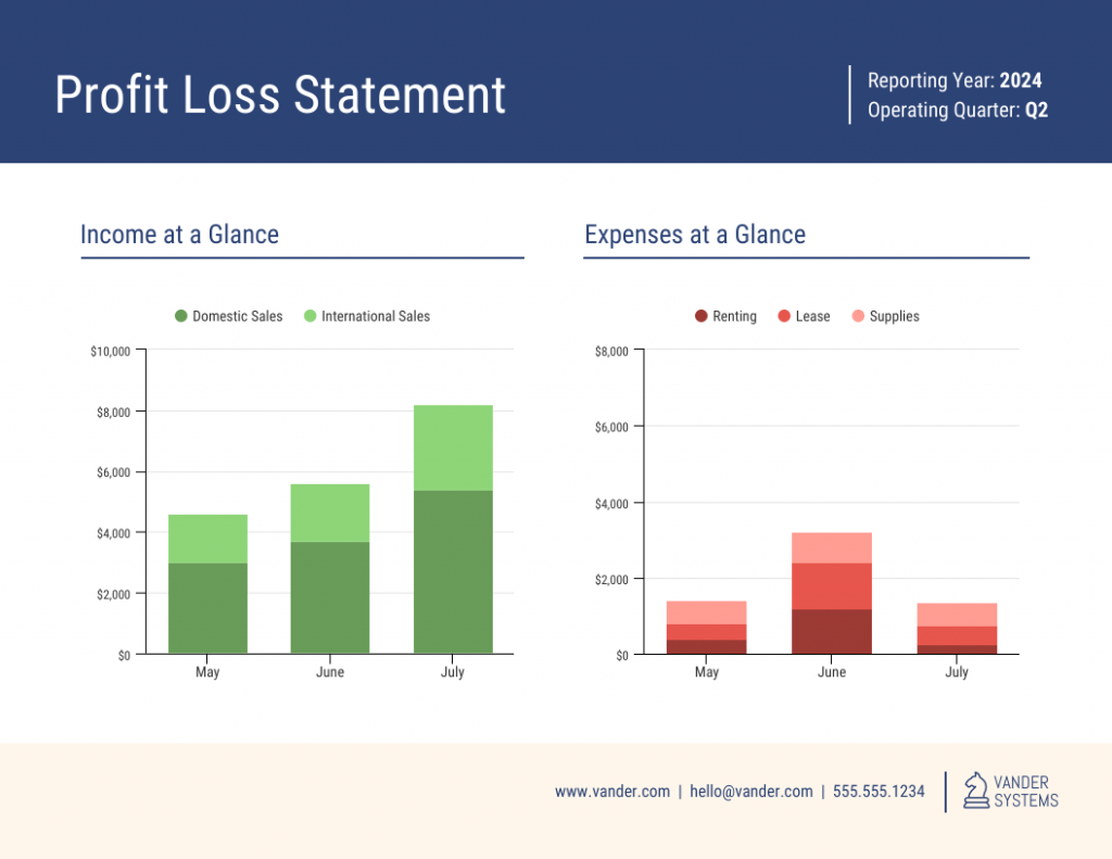
This method is ideal for highlighting both the individual and collective significance of each component, making it a valuable tool for comparative analysis.
Stacked bar charts are like data sandwiches—label each layer so people know what’s what. Keep the order logical and don’t forget the paintbrush for snazzy colors. Here’s a data analysis presentation example on writers’ productivity using stacked bar charts:

7. Area chart
Similar to line charts but with the area below the lines filled, making them suitable for showing cumulative data.
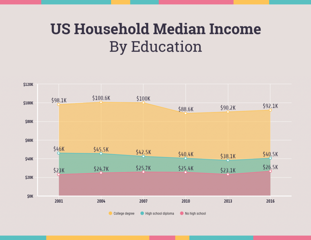
Area charts are close cousins of line charts but come with a twist.
Imagine plotting the sales of a product over several months. In an area chart, the space between the line and the x-axis is filled, providing a visual representation of the cumulative total.

This makes it easy to see how values stack up over time, making area charts a valuable tool for tracking trends in data.
For area charts, use them to visualize cumulative data and trends, but avoid overcrowding the chart. Add labels, especially at significant points and make sure the area under the lines is filled with a visually appealing color gradient.
8. Tabular presentation
Presenting data in rows and columns, often used for precise data values and comparisons.
Tabular data presentation is all about clarity and precision. Think of it as presenting numerical data in a structured grid, with rows and columns clearly displaying individual data points.
A table is invaluable for showcasing detailed data, facilitating comparisons and presenting numerical information that needs to be exact. They’re commonly used in reports, spreadsheets and academic papers.

When presenting tabular data, organize it neatly with clear headers and appropriate column widths. Highlight important data points or patterns using shading or font formatting for better readability.
9. Textual data
Utilizing written or descriptive content to explain or complement data, such as annotations or explanatory text.
Textual data presentation may not involve charts or graphs, but it’s one of the most used qualitative data presentation examples.
It involves using written content to provide context, explanations or annotations alongside data visuals. Think of it as the narrative that guides your audience through the data.
Well-crafted textual data can make complex information more accessible and help your audience understand the significance of the numbers and visuals.
Textual data is your chance to tell a story. Break down complex information into bullet points or short paragraphs and use headings to guide the reader’s attention.
10. Pictogram
Using simple icons or images to represent data is especially useful for conveying information in a visually intuitive manner.
Pictograms are all about harnessing the power of images to convey data in an easy-to-understand way.
Instead of using numbers or complex graphs, you use simple icons or images to represent data points.
For instance, you could use a thumbs up emoji to illustrate customer satisfaction levels, where each face represents a different level of satisfaction.

Pictograms are great for conveying data visually, so choose symbols that are easy to interpret and relevant to the data. Use consistent scaling and a legend to explain the symbols’ meanings, ensuring clarity in your presentation.

Looking for more data presentation ideas? Use the Venngage graph maker or browse through our gallery of chart templates to pick a template and get started!
A comprehensive data presentation should include several key elements to effectively convey information and insights to your audience. Here’s a list of what should be included in a data presentation:
1. Title and objective
- Begin with a clear and informative title that sets the context for your presentation.
- State the primary objective or purpose of the presentation to provide a clear focus.

2. Key data points
- Present the most essential data points or findings that align with your objective.
- Use charts, graphical presentations or visuals to illustrate these key points for better comprehension.

3. Context and significance
- Provide a brief overview of the context in which the data was collected and why it’s significant.
- Explain how the data relates to the larger picture or the problem you’re addressing.
4. Key takeaways
- Summarize the main insights or conclusions that can be drawn from the data.
- Highlight the key takeaways that the audience should remember.
5. Visuals and charts
- Use clear and appropriate visual aids to complement the data.
- Ensure that visuals are easy to understand and support your narrative.

6. Implications or actions
- Discuss the practical implications of the data or any recommended actions.
- If applicable, outline next steps or decisions that should be taken based on the data.

7. Q&A and discussion
- Allocate time for questions and open discussion to engage the audience.
- Address queries and provide additional insights or context as needed.
Presenting data is a crucial skill in various professional fields, from business to academia and beyond. To ensure your data presentations hit the mark, here are some common mistakes that you should steer clear of:
Overloading with data
Presenting too much data at once can overwhelm your audience. Focus on the key points and relevant information to keep the presentation concise and focused. Here are some free data visualization tools you can use to convey data in an engaging and impactful way.
Assuming everyone’s on the same page
It’s easy to assume that your audience understands as much about the topic as you do. But this can lead to either dumbing things down too much or diving into a bunch of jargon that leaves folks scratching their heads. Take a beat to figure out where your audience is coming from and tailor your presentation accordingly.
Misleading visuals
Using misleading visuals, such as distorted scales or inappropriate chart types can distort the data’s meaning. Pick the right data infographics and understandable charts to ensure that your visual representations accurately reflect the data.
Not providing context
Data without context is like a puzzle piece with no picture on it. Without proper context, data may be meaningless or misinterpreted. Explain the background, methodology and significance of the data.
Not citing sources properly
Neglecting to cite sources and provide citations for your data can erode its credibility. Always attribute data to its source and utilize reliable sources for your presentation.
Not telling a story
Avoid simply presenting numbers. If your presentation lacks a clear, engaging story that takes your audience on a journey from the beginning (setting the scene) through the middle (data analysis) to the end (the big insights and recommendations), you’re likely to lose their interest.
Infographics are great for storytelling because they mix cool visuals with short and sweet text to explain complicated stuff in a fun and easy way. Create one with Venngage’s free infographic maker to create a memorable story that your audience will remember.
Ignoring data quality
Presenting data without first checking its quality and accuracy can lead to misinformation. Validate and clean your data before presenting it.
Simplify your visuals
Fancy charts might look cool, but if they confuse people, what’s the point? Go for the simplest visual that gets your message across. Having a dilemma between presenting data with infographics v.s data design? This article on the difference between data design and infographics might help you out.
Missing the emotional connection
Data isn’t just about numbers; it’s about people and real-life situations. Don’t forget to sprinkle in some human touch, whether it’s through relatable stories, examples or showing how the data impacts real lives.
Skipping the actionable insights
At the end of the day, your audience wants to know what they should do with all the data. If you don’t wrap up with clear, actionable insights or recommendations, you’re leaving them hanging. Always finish up with practical takeaways and the next steps.
Can you provide some data presentation examples for business reports?
Business reports often benefit from data presentation through bar charts showing sales trends over time, pie charts displaying market share,or tables presenting financial performance metrics like revenue and profit margins.

What are some creative data presentation examples for academic presentations?
Creative data presentation ideas for academic presentations include using statistical infographics to illustrate research findings and statistical data, incorporating storytelling techniques to engage the audience or utilizing heat maps to visualize data patterns.
What are the key considerations when choosing the right data presentation format?
When choosing a chart format , consider factors like data complexity, audience expertise and the message you want to convey. Options include charts (e.g., bar, line, pie), tables, heat maps, data visualization infographics and interactive dashboards.
Knowing the type of data visualization that best serves your data is just half the battle. Here are some best practices for data visualization to make sure that the final output is optimized.
How can I choose the right data presentation method for my data?
To select the right data presentation method, start by defining your presentation’s purpose and audience. Then, match your data type (e.g., quantitative, qualitative) with suitable visualization techniques (e.g., histograms, word clouds) and choose an appropriate presentation format (e.g., slide deck, report, live demo).
For more presentation ideas , check out this guide on how to make a good presentation or use a presentation software to simplify the process.
How can I make my data presentations more engaging and informative?
To enhance data presentations, use compelling narratives, relatable examples and fun data infographics that simplify complex data. Encourage audience interaction, offer actionable insights and incorporate storytelling elements to engage and inform effectively.
The opening of your presentation holds immense power in setting the stage for your audience. To design a presentation and convey your data in an engaging and informative, try out Venngage’s free presentation maker to pick the right presentation design for your audience and topic.
What is the difference between data visualization and data presentation?
Data presentation typically involves conveying data reports and insights to an audience, often using visuals like charts and graphs. Data visualization , on the other hand, focuses on creating those visual representations of data to facilitate understanding and analysis.
Now that you’ve learned a thing or two about how to use these methods of data presentation to tell a compelling data story , it’s time to take these strategies and make them your own.
But here’s the deal: these aren’t just one-size-fits-all solutions. Remember that each example we’ve uncovered here is not a rigid template but a source of inspiration. It’s all about making your audience go, “Wow, I get it now!”
Think of your data presentations as your canvas – it’s where you paint your story, convey meaningful insights and make real change happen.
So, go forth, present your data with confidence and purpose and watch as your strategic influence grows, one compelling presentation at a time.
Discover popular designs
Infographic maker
Brochure maker

White paper online
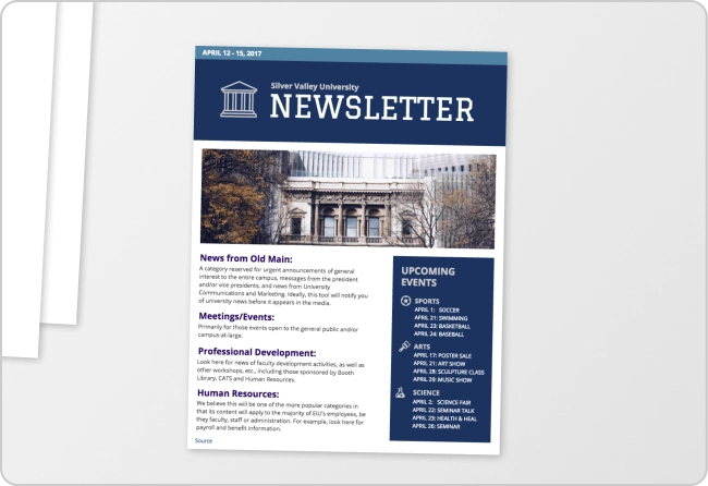
Newsletter creator
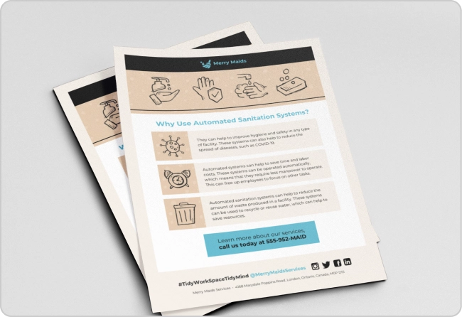
Flyer maker
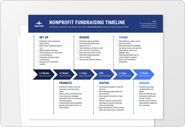
Timeline maker
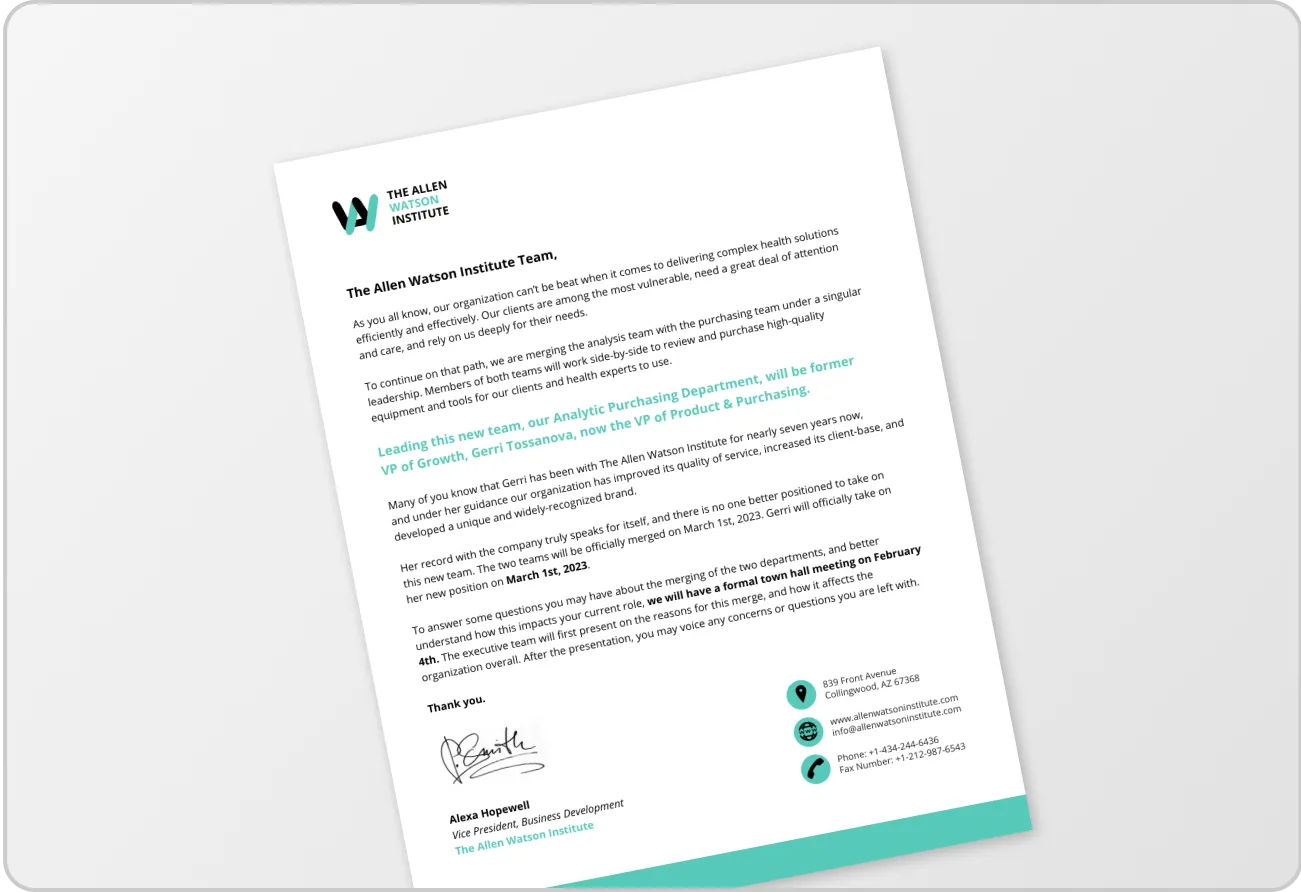
Letterhead maker
Mind map maker
Ebook maker

- My presentations
Auth with social network:
Download presentation
We think you have liked this presentation. If you wish to download it, please recommend it to your friends in any social system. Share buttons are a little bit lower. Thank you!
Presentation is loading. Please wait.
Data Communication Topics to be discussed: Data Communication Terminology. Data Transmission Signals. Data Transmission Circuits. Serial & Parallel.
Published by Willie Seger Modified over 9 years ago
Similar presentations
Presentation on theme: "Data Communication Topics to be discussed: Data Communication Terminology. Data Transmission Signals. Data Transmission Circuits. Serial & Parallel."— Presentation transcript:

DATA COMMUNICATION AND NETWORKING Chapter 12. Communication sending or receiving information Beating of drums Mirrors reflecting sunlight Homing pigeons.
Copyright : Hi Tech Criminal Justice, Raymond E. Foster Police Technology Police Technology Chapter Four Police Technology Networks.

Transmission Basics ITNW 1325, Chapter III. OSI Physical Layer.

Physical Layer CHAPTER 3. Announcements and Outline Announcements Credit Suisse – Tomorrow (9/9) Afternoon – Student Lounge 5:30 PM Information Session.

Chapter 1. Understand bits, bytes, megabytes, etc. Learn basic communication model. Learn the distinction between channel, circuit and network.

Csc333 Data communication & Networking Credit: 2.

Assessment 1 Review Network Layers. Computer 1Computer 2 2.

Telecommunications Long distance communication May or may not involve computers.

Chapter 8 Data and Network Communication Technology

CS335 Networking & Network Administration Tuesday, April 6.

© 2007 Pearson Education Inc., Upper Saddle River, NJ. All rights reserved.1 Computer Networks and Internets with Internet Applications, 4e By Douglas.

1 Chapter 7 Networking: Computer Connections. Basic Components of a Network Sending device Communications link Receiving device.

Module 3.0: Data Transmission

Chapter 2 : Business Information Business Data Communications, 4e.

Chapter 1: Introduction Business Data Communications, 4e.

Learning Outcomes Know the basic components of a network Know data transmission methods, including types of signals, modulation, demodulation, and.

1 Fall 2005 Long Distance Communication Carriers, Modulation, And Modems Qutaibah Malluhi Computer Science and Engineering Qatar University.

Data Communications Chapter 6 The Data Communications Interface.

Chapter Preview In this chapter, we will study: The basic components of a telecomm system The technologies used in telecomm systems Various ways.

Chapter 8 COMMUNICATION AND COMPUTER NETWORK
About project
© 2024 SlidePlayer.com Inc. All rights reserved.
Understanding Data Communications: Concepts and Techniques
Aug 14, 2024
510 likes | 528 Views
Explore essential definitions, analog versus digital systems, encoding techniques, and more in data communications. Learn how data are encoded into signals and transmitted effectively.
Share Presentation
- data communications
- transmission systems
- encoding techniques
- encoding schemes
- data transmission

Presentation Transcript
Chapter 2 – Topics in Data Communications
Data Communications ConceptsIntroduction • Essential definitions for Data Communications • Data, Signaling, & Transmission Systems • Analog & Digital • Data are entities that convey meaning, while signaling is the transfer of encoded data thru a transmission system • Analog versus digital signaling • Digital signaling usually less expensive than analog but care must be taken to properly engineer system (e.g. - attenuation) • Combinations of analog & digital data and signals • Analog data -> Analog signals • Digital data -> Analog signals (Key equipment is a modem) • Analog data -> Digital signals (Key equipment is a codec) • Digital data -> Digital signals
Data Communications ConceptsAnalog versus Digital Transmission Systems • Analog systems transmit analog signals without regard for the content of the signal • Amplifiers are used to boost the energy of the signal • Amplifiers also boost the strength of any noise on the line, introducing the possibility that the signal could be lost • Digital Transmission Systems are concerned with the content of the signal • Repeaters used to regenerate the signal, overcoming attenuation • Repeaters output a new copy cleansed of any noise, so noise is not cumulative (however, bit errors can still occur if the signal is not regenerated before it degrades too much)
Data Encoding TechniquesIntroduction • Encoding is the process of mapping digital data into the appropriate signal elements for transmission • Encoding may be very complex or as simple as using binary signal elements (0s and 1s) • Encoding schemes are chosen to assist the receiver in its two key tasks: • Determining when the signal element begins and ends (so sampling is done at the proper time) • Determining the value of the signal element (Is it a one? A zero?) • Attenuation, data rate, & noise all play a role at receiver • With analog data the encoding scheme also plays a key role in system performance but the details are a little different
Data Encoding TechniquesAnalog encoding of digital data • The basis for analog encoding is a base signal called the carrier signal • Digital data is encoded (and decoded at the other end) by a device called a modem • Three basic schemes for analog encoding of digital data: • Amplitude Shift-keying (ASK) • Frequency Shift-keying (FSK) • Phase Shift-keying (PSK) • These schemes can be combined for more sophisticated digital transmission systems that carry more data per signal element
Data Encoding TechniquesAnalog encoding of digital data • Amplitude-shift Keying • Data represented by different amplitude levels of the carrier signal • Simplest scheme, but inefficient and prone to noise • Most valuable use is in optical systems • Frequency-shift Keying • Data represented by different frequency values near the carrier signal frequency • Less prone to errors but requires more complex circuitry • Phase-shift Keying • Data represented by different phase shifts to the carrier frequency • More efficient and noise resistant than ASK or FSK but requires more complex circuitry
Data Encoding TechniquesDigital Encoding of Digital Data • The most common way to encode digital data is to use a binary signaling scheme consisting of two voltage levels • NRZ-L (Non-Return to Zero Level) • Each voltage level defines the value of the digital data • Used only in very short connections • NRZ-I (Non-Return to Zero Inverted) • A transition at the beginning of a signal unit denotes a binary one • This type of signaling is known as differential signaling; it is usually easier to detect a transition out of the background noise and the signals are polarity insensitive • Clocking and DC current are usually problems
Data Encoding TechniquesDigital Encoding of Digital Data • Manchester Encoding • Example of a bi-phase coding; up to two signaling transitions per signal element (needs more bandwidth to transmit a given data rate) • The mid-signal transition provides clocking as well as the data value (a zero data element is a high-to-low transition and a one is a low-to-high transition) • Used in Ethernet LANs (IEEE 802.3) • Differential Manchester Encoding • Another bi-phase code • The mid-signal transition provides clocking; the transition at the beginning of the signal element represents data (a zero data element has no transition at the beginning of a bit time while a one does) • Used in Token Ring LANs (IEEE 802.5)
Data Encoding TechniquesDigital Encoding of Analog Data • Pulse Code Modulation (PCM) is an example – used in the phone system to transmit analog data across digital networks • Sampling rate based on the Nyquist theorem • Digitized into 8 bit samples based on a nonlinear scale that provides good reproduction of the human voice • Other digital-to-analog encoding schemes: • Adaptive Differential Pulse Code Modulation (ADPCM) - used with voice transmission • Delta Modulation - used rarely but also for voice transmission systems • Code Excited Linear Prediction (CELP) - used in very low-bandwidth voice and multimedia communication systems
MultiplexingIntroduction • Allows a transmission system to carry multiple independent signals simultaneously for higher efficiency • Two general schemes are in use: FDM and TDM • Frequency Division Multiplexing (FDM) • Takes advantage of the fact that the useful bandwith of the transmission system exceeds the required bandwidth of a given signal • Allows frequency spectrum to be divided & allocated to different signal sources • Most commonly used with analog signaling and transmission • Time Division Multiplexing (TDM)
MultiplexingTechniques • Allows a transmission system to carry multiple independent signals simultaneously for higher efficiency • Two general schemes are in use: FDM and TDM • Time Division Multiplexing (TDM) • Takes advantage of the fact that the maximum bit rate of the system exceeds the required bit rate of the digital signal • Each source is allocated a ‘time slot’ in the multiplexer • Analog signals can be time division multiplexed, but it is very uncommon • Two varieties of TDM: statistical and fixed time-slot • Both FDM and TDM can be used in a synchronous or asynchronous manner
Transmission MediaIntroduction • The transmission media is the physical signal path between the transmitter and the receiver • Can be guided (cables, waveguides, etc.) or unguided (open air) • Our key concerns for transmission systems are data rate and distance • Influencing factors: • Bandwidth of the media • Transmission impairments • Interference • Number of Receivers
Transmission Media (2)Twisted Pair Cable • Consists of a minimum of two copper wires twisted together and enclosed within a protective sheath • Advantages: inexpensive, easy to work with, may already be installed where needed • Disadvantages: limited in distance, data rate, and bandwidth; susceptible to interference • Comes in two general varieties: shielded twisted pair (STP) and unshielded twisted pair (UTP) • Shielding provides more noise immunity, especially at lower data rates • STP costs more and is more difficult to work with
Transmission Media (3)Twisted Pair Cable • Category 3 and Category 5 UTP • Rating standards devised by the Electronic Industries Association (EIA) • The higher the category the better the cable; Cat 3 designed to support 10Mbps Ethernet while Cat 5 will support 100Mbps Ethernet • The key difference between the two categories is the number of twists per unit length of cable • Near-end Crosstalk (NEXT) is a key transmission impairment to minimize in any twisted pair cabling system • While these are regarded as the most commonly found UTP installations, there are higher performance UTP choices
Transmission MediaTwisted Pair Cable • High-performance Twisted Pair • Category 5e (or enhanced Category 5): supports 125-MHz bandwidth on all four pairs, allowing Gigabit Ethernet to run over UTP up to 100 meters • Attenuation (db/100m)=12.3 for 100 MHz, 12.3=-10Log(Vin/Vout) gives Log(Vin/Vout)=-1.23 or Vin/Vout is about 1/10 (tenth of signal magnitude exits from the UTP. • Crosstalk=32db=-10Log(Vneighbor/Vsignal), about 1/1000 crosstalk. • Cat 5 UTP provides 100 Mbps over 100m. • Category 6: supports over 200-MHz bandwidth on all four pairs; could potentially run high data rate ATM connections • Category 7: will require special shielding and will likely support up to 700-MHz bandwidth on each pair
Transmission MediaCoaxial Cable • Provides a two conductor transmission system where one conductor is situated inside the outer hollow conductor with an insulating dielectric in between • Because of its structural characteristics coaxial cable is more resistant to noise than twisted pair • Harder to work with and more expensive than twisted pair • Coax systems can be grouped in three categories based on the type of signaling used: • Baseband: digital signaling occupies the entire spectrum of the cable • Broadband: carrier-band analog signaling is used, allowing multiple channels on the cable • Carrierband: carrier-band analog signaling with low-end components; signal occupies entire spectrum of cable • Coaxial cable provides 100 Mbps over 1Km.
Transmission MediaFiber Optic Cabling • A transmission system composed of a guided medium that allows the propagation of optical rays • A range of fiber optic cabling exists for various needs, from ultra-pure fused silica (expensive but high data rate) to plastic (cheap with lower data rate for short runs) • Advantages • Huge bandwidth capacity • Smaller size and lightweight • Lower attenuation • Electromagnetic isolation (high security & minimal interference) • 100 Gbps over 10 Km (multimode fiber) • Common transmitters used are LEDs for (low-cost & low-speed systems) or Injection Laser Diodes (long-haul high-speed systems)
Transmission MediaFiber Optic Cabling • Basic fiber types • Step-index multimode: cheapest to manufacture but allows light to travel different paths down the fiber, causing signal distortion & lowering the maximum data rate. • Graded-index multimode: Higher grade of fiber with a varying refractive index that limits distortion of the signal. • Singlemode: contains a core with a diameter close to the wavelength to be transmitted; allows only a single transmission path down the fiber which practically eliminates distortion • Three wavelength ‘windows’ provide the best light propagation: 850, 1300, & 1550 nm • Most multimode systems use the 850 nm window • Long-haul transmission systems use the 1550 nm window because loss is lower at higher wavelengths
Transmission MediaUnguided Media • Microwave • Occupies the frequency spectrum from 1GHz to 30GHz; can provide either a highly directional or omni-directional system • There are 3 main challenges to using microwave for data transmission: • Frequency Allocation and licensing • Interference • Security • Infrared • Uses light in the infrared spectrum for data transmission • Must be used line-of-sight or in an environment that allows infrared waves to be reflected • Less issues associated with microwave but only for specialized uses
Data Communication NetworksIntroduction • For most WAN and MANs, transmission of data usually involves a number of intermediate switching nodes that move the data between source and destination • The complete set of end nodes, data links, & intermediate switches is known as a communications network • There is a spectrum of communication switching techniques; the two main variations are circuit and packet switching
Data Communication NetworksCircuit Switching • Communication between end nodes is via a dedicated communications channel • Communications via circuit switching involves three phases: • Circuit establishment: the path is established before any data is transferred. The path is digital or analog and may include internal links operated using TDM or FDM. • Data transfer • Circuit disconnect: release of resource dedicated to the connection • The fixed capacity of the channel is allocated for the duration of the connection; can be very inefficient with bursty traffic (repeatedly ON during T and OFF later) • Circuit switching is best suited for synchronous data such as voice or real-time video
Data Communication NetworksPacket Switching • Packet switching breaks data up into a series of packets, each appended with enough control information to ensure the packet transits the network successfully from source to destination • Developed to address problems certain data sources have with circuit switching: • Bursty data transmission • Source and destination must operate at the same data rate • Inefficient resource allocation • Connection setup can be too slow for certain applications (set up Virtual Circuit along logical connection path links, send packets without routing decision over VC) • In addition to addressing the above problems, packet switching also has other benefits for data transmission: • Under heavy load the network will accept packets but delay increases • Priorities for transmission of the packets can be set • Data rate conversion along links with short store and forward
Data Communication NetworksPacket Switching • Two main varieties: datagrams or virtual circuits • Datagram Approach: Each packet is routed independently of all others, leading to the following consequences: • Packets don’t take the same routes, may arrive out of sequence • Routing based on neighboring info on traffic and failure • Possible packet discard (overflow in queues) and no control-flow • No circuit setup time, so data flow begins without delay • Data can easily flow around problems in the network • Virtual Circuit Approach: a preplanned route through the network is established before any data is sent • Requires logical circuit setup and teardown but routes along the connection are shared (identical) with other packets • A routing decision does not have to be made for every packet • May provide enhanced services such as error & flow control, and packet sequencing not available in a datagram environment
Problem: M bit to be transmitted using UDP and Virtual Circuit (VC). t(UDP) and t(VC) is routing overhead for UDP and VC for each link. There are K links on the path. The largest packet has only N bits and data rate is R. Under what condition UDP and VC have the same transmission time. Using UDP: T(UDP)= kM/N(1/R+t(UDP)) Using VC: T(UDP)= k(t(VC) + M/NR) The same transmission time when kMt(UDP)/N =kt(VC). However, UDP produces shorter time when M/N is small.
Data Communication NetworksHybrids • Multi-rate Circuit Switching (to improve circuit switching) • Extends circuit switching to allow one or more fundamental channels to be bundled together to provide a range of data connection rates • Examples of multi-rate switching are ISDN (2x64 Kbps and 1x16Kbps channels) and inverse multiplexing • Frame Relay (FR) • Packet switching was operating under high error rate and overhead added to enhance redundancy and reduce errors which produced the FR scheme (from 64 Kbps to 2 Mbps by removing overhead). • WAN service based on a connection-oriented packet data protocol • Frame Relay evolved from X.25; the new protocol was streamlined by eliminating features necessary on earlier, less reliable X.25 data communications networks • Cell Relay (ATM) • A further evolution of connection-oriented packet data services • Unlike frame relay fixed length data units (cells) are used which allow high-speed hardware based switching • Connection oriented, fixed cell size, fast switching devices.
Comparison Packet Switching vs. Circuit Switching Is packet switching a “clear winner?” • Great for bursty data • Resource sharing • No call setup • Excessive congestion: packet delay and loss • Protocols needed for reliable data transfer, congestion control • Q: How to provide circuit-like behavior? • Bandwidth guarantees needed for audio/video apps • Still an unsolved problem
Routing Routing in Packet-Switched Networks • Goal: move packets among routers from source to destination • We’ll study several path selection algorithms (chapter 5) • Datagram network: • Destination address determines next hop • Routes may change during session • Analogy: postal service • Virtual circuit network: • Each packet carries tag (virtual circuit ID), tag determines next hop • Fixed path determined at call setup time, remains fixed through call • Routers maintain per-call state
Telecommunication networks Circuit-switched networks Packet-switched networks FDM TDM VC Based networks Datagram networks Taxonomy
Network Access • End hosts are connected to edge routers through access networks • Types of access networks: • Residential access • Company access • Mobile access • Types of physical media technologies for access networks: • Fiber • Coaxial cable • Twisted-pair telephone wire • Radio spectrum
Access Network Access Network: Residential Access • Connects home end systems to the network edge • Typically, through an ISP • End hosts are PCs • AKA last mile • Means of residential access: dialup, DSL, Cable, etc. • Dial-up modem • Uses POTS line twisted pair copper wire • Calls ISP’s number • Max. data rate: 56 Kbps • Phone line is tied up when connected to ISP • Digital Subscriber Line (DSL) • Does not tie up the phone line • Uses existing twisted-pair line • Asymmetric upstream and downstream data rates • Downstream: 384 Kb/s—1.5 Mb/s • Upstream: 128—256 Kb/s • Hybrid Fiber Coaxial (HFC) Cable • Utilizes distribution network of video broadcast cable • Cable modem uses two channels for data transmission • Shared among subscribers • 10 Base-T Ethernet port
LAN access LAN access • Company/university local area network (LAN) connects end system to edge router • Ethernet: • Shared or dedicated cable connects end system and router • 10 Mbs, 100Mbps, Gigabit Ethernet • Deployment: institutions, home LANs soon • LANs: Link layer (chapter 5) Wireless Access Networks • Shared wireless access network connects mobile end system to router at a base station • Laptops, PDAs, etc. • Wireless LANs: • Radio spectrum replaces wire • Wireless LANs are based on IEEE 802.11 b standard (11 Mbps) • Wider-area wireless access • CDPD (Cellular Digital Packet Data): wireless access to ISP router via cellular network • Third Generation (3G) wireless: packet-switched wide-area Internet access at 384 Kbps
Example 1 • How long will it take to send a file of 640,000 bits from host A to host B over a circuit-switched network. • Suppose all links in the network are TDM with: • 24 slots and • have a bit rate of 1.536Mbps • It takes 500 msec to establish an end-to-end circuit before host A begins transmitting to B • How long will it take to send file?
Example 1 • How long will it take to send a file of 640,000 bits from host A to host B over a circuit-switched network. • Suppose all links in the network are TDM with: • 24 slots and • have a bit rate of 1.536Mbps • It takes 500 msec to establish an end-to-end circuit before host A begins transmitting to B • How long will it take to send file? • Transmission rate for each circuit = 1.536 Mbps / 24 = 64 Kbps • Time to send 640 Kbits file = (640000 bits)/(64 Kbits/sec) = 10 seconds • Including circuit setup overhead, time to send file is 10.5 seconds • This calculation is independent of the # of end-to-end links and does not include propagation delays
Example 2 Packet Switching: • Two forwarding mechanisms: • No segmentation message switching • With segmentationpipelining • Example: 7.5 million bits message sent over 3 links, each of 1.5 Mbps • Time required without segmentation = (7.5/1.5)x3=15 sec • Now segment packet into 5000 chunks each of 1500 bits • Time for whole packet = 5.002 sec • Pipelining results in reduction of delays as all links are being utilized simultaneously
Delay in Packet-Switched networks Transmission delay: • R=link bandwidth (bps) • L=packet length (bits) • Time to send bits into link = L/R Propagation delay: • d = length of physical link • s = propagation speed in medium (~2x10⁸ m/sec) • Propagation delay = d/s
Example 3 Packet Switching Calculation of delay: • A packet of L bits • Q links between source and destination hosts • Each link has a data rate of R bits/sec • Assume: • No queuing delays • No end-to-end propagation delays • No connection establishment is required • How long it takes to send this L bit packet from source to destination? • Time to traverse the first link from source host: L/R seconds • Q-1 more such links are traversed before reaching destination • Thus, total delay: QL/R seconds more delay for larger packets
Example: LAN Hierarchy • N stations to be arranged in a LAN hierarchy • Each ST transfers on the average M bits per second, of which qM are to STs that are local to its segment and (1-q)M to STs in other segments • How to arrange the LAN Hierarchy so that traffic in one LAN segment does not exceed the segment capacity B, where B is 0.8xData.Rate of a LAN segment, i.e. a reference to a congestion point.
Solution • Suppose there are K segments each consists of N/K stations, where k rages from 1 (1 seg) to N (N segs). • In a segment, the locally destined traffic by is qMN/K • In a segment, the exported traffic by is (1-q)MN/K • In a segment, the imported traffic by is (1-q)MN/K, because: • there are (K-1) segments each generates (1-q)MN/K external traffic, • Total external traffic for K-1 segments is (K-1)(1-q)MN/K destined to (k-1) segments. • Thus, a segment imports (1-q)MN/K data. • Total traffic for a segment is Q= qMN/K (local) + (1-q)MN/K (exported) + (1-q)MN/K (imported)=MN/K + (1-q)MN/K= MN(2-q)/K • Let’s derivate Q w.r.t. K to find its minimum value: dQ/dK=-MN(2-q)/K^2 which is minimum for K maximum or K=N. • We may incease the number of STs in a segment until Q(K)=0.8xData.Rate or MN(2-q)/K <= 0.8xData.Rate or • MN(2-q)/(0.8xData.Rate) <= K.
wireless transmission • • Wireless local area networks (e.g IEEE 802.11) • – 2.4 GHz (microwave band) 1-2 Mbps, 150 m • – Infrared (IR) link 1-10 Mbps, 10 m • • Earth based cellular data • – Basic individual connection, 13 Kbps, 3 km • – Higher rate PCS (e.g. EDGE), 384 Kbps, 3 km • • Satellite links (GHz frequencies) • – geosynchronous, 600-1000 Mbps, continent • – Low earth orbit (LEO) 13 kbps - 400 Mbps, 800 km • (e.g., Motorola Iridium, 66 satellite constellation) services available from carriers • Integrated Services Digital Network (ISDN) 144 Kbps • Asymmetric Digital Subscriber Lines 1.5-8 Mbps/16-640 Kbps • Cable modems 0.5-2 Mbps • T1 (old electronic telephony standard) 1.544 Mbps • T2 6.312 Mbps • T3 44.736 Mbps • Synchronous Transport Signal-1 (STS-1) 51.840 Mbps • STS-3 (a common ATM rate) 155.250 Mbps • STS-12 (another common ATM rate) 622.080 Mbps • STS-24 1.244160 Gbps • etc.
- More by User
Data Communications
Data Communications. Chapter 1 – Data Communications, Data Networks, and the Internet. Eighth Edition by William Stallings. Data Communications, Data Networks, and the Internet.
765 views • 29 slides
CHAPTER 6. DATA COMMUNICATIONS. Components of a Basic Data Communications Link. Data Networks Terminology. Data Network Collaborative environment that provides worldwide access to corporate data Network Architecture
849 views • 60 slides
Data Communications and Networking
Data Communications and Networking. Chapter 9 High Speed LAN s and Wireless LANs References: Book Chapters 16 and 17 Data and Computer Communications, 8th edition By William Stallings. Outline. Fundamentals of Ethernet ALOHA, slotted ALOHA, CSMA CSMA/CD Ethernet Examples
812 views • 40 slides
Chapter 9 Communications and Networks
Chapter 9 Communications and Networks. Chapter 9 Objectives. Next. Discuss the components required for successful communications. Explain the purpose of communications software. Identify various sending and receiving devices.
717 views • 49 slides

Data Communications and Networking. Chapter 6 Multiplexing References: Book Chapter 6 Data and Computer Communications, 6th edition, by William Stallings. Schedule. Signal encoding: 5 hours Multiplexing: 1 hour Error detection & correction: 2 hours Flow control & error control: 3 hours
466 views • 17 slides

Chapter 8 Communications and Networks
Chapter 8 Communications and Networks. Chapter 8 Objectives. Next. Discuss the components required for successful communications. Describe various types of lines for communications over the telephone network. Describe commonly used communications devices.
664 views • 46 slides
Data and Computer Communications
Data and Computer Communications. Chapter 6 – Digital Data Communications Techniques. Ninth Edition by William Stallings. Digital Data Communications Techniques.
388 views • 20 slides
Data Communications and Networks
Data Communications and Networks. Chapter 10 – Network Hardware and Software. ICT-BVF8.1- Data Communications and Network Trainer: Dr. Abbes Sebihi. Agenda. Objective;
416 views • 13 slides

Data and Computer Communications. Tenth Edition by William Stallings. Chapter 1. Data Communications, Data Networks, and the Internet. “The fundamental problem of communication is that of reproducing at one point either exactly or approximately a message selected at another point”
3.79k views • 33 slides

Data and Computer Communications. Chapter 1 – Data Communications, Data Networks, and the Internet. Ninth Edition by William Stallings. Data Communications, Data Networks, and the Internet.
659 views • 37 slides

Data and Computer Communications. Uzma Afzal. Main Idea. Data? Communication?. Remarkable Facts. There is no fundamental difference between data processing ( computers) and data communications (transmission and switching equipment).
436 views • 16 slides

Data Communications and Networks. Chapter 5 – Network Services DNS, DHCP, FTP and SMTP. ICT-BVF8.1- Data Communications and Network Trainer: Dr. Abbes Sebihi. Agenda. Objective;
500 views • 24 slides
COE 341: Data & Computer Communications (T081) Dr. Marwan Abu-Amara
COE 341: Data & Computer Communications (T081) Dr. Marwan Abu-Amara. Chapter 1: Data Communications & Networking Overview. Acknowledgements. Many figures, slides, and course notes were made available by: Pearson Prentice-Hall Data & Computer Communications, W. Stallings McGraw-Hill
477 views • 19 slides
Chapter 1. The Data Communications Industry. Objectives of Chapter 1. To understand the meaning of data communications To study the basic components of data communications as an industry To understand standards and regulations
686 views • 59 slides
Data cleaning Data cleaning: An overview Error detection (Chapter 3) Data repairing (Chapter 3)
TDD: Research Topics in Distributed Databases. Data cleaning Data cleaning: An overview Error detection (Chapter 3) Data repairing (Chapter 3) Taking record matching and data repairing together (Chapter 7) Certain fixes (Chapter 7). A platform for improving data quality. profiling.
652 views • 45 slides

659 views • 46 slides
Chapter 2. Data Communications Concepts. What We’ll Be Covering. Data Communications Concepts: Data Communications Architecture Data Digitization Data Transmission Techniques Data Communication Techniques Error Control Techniques. Overall Data Communications Architecture.
747 views • 57 slides
Data Communications & Networking
Data Communications & Networking. Chapter 1 - Introduction. Data Communication. Data communication – exchange of data between two devices via a transmission medium. Communication System Components. Data Representation. Text – represented as a bit pattern; codes often used:
719 views • 22 slides

619 views • 49 slides
William Stallings Data and Computer Communications
William Stallings Data and Computer Communications. Chapter 1 Introduction. A Communications Model . Source generates data to be transmitted Transmitter Converts data into transmittable signals Transmission System Carries data Receiver Converts received signal into data Destination
643 views • 41 slides
JavaScript seems to be disabled in your browser. For the best experience on our site, be sure to turn on Javascript in your browser.
Newly Launched - AI Presentation Maker

- Customer Favourites
Data Communication
AI PPT Maker
Powerpoint Templates
PPT Bundles
Kpi Dashboard
Professional
Business Plans
Swot Analysis
Gantt Chart
Business Proposal
Marketing Plan
Project Management
Business Case
Business Model
Cyber Security
Business PPT
Digital Marketing
Digital Transformation
Human Resources
Product Management
Artificial Intelligence
Company Profile
Acknowledgement PPT
PPT Presentation
Reports Brochures
One Page Pitch
Interview PPT
All Categories

- You're currently reading page 1
Stages // require(['jquery'], function ($) { $(document).ready(function () { //removes paginator if items are less than selected items per page var paginator = $("#limiter :selected").text(); var itemsPerPage = parseInt(paginator); var itemsCount = $(".products.list.items.product-items.sli_container").children().length; if (itemsCount ? ’Stages’ here means the number of divisions or graphic elements in the slide. For example, if you want a 4 piece puzzle slide, you can search for the word ‘puzzles’ and then select 4 ‘Stages’ here. We have categorized all our content according to the number of ‘Stages’ to make it easier for you to refine the results.
Category // require(['jquery'], function ($) { $(document).ready(function () { //removes paginator if items are less than selected items per page var paginator = $("#limiter :selected").text(); var itemsperpage = parseint(paginator); var itemscount = $(".products.list.items.product-items.sli_container").children().length; if (itemscount.
- 3D Man (35)
- Anatomy (2)
- Block Chain (28)
- Branding (39)
- Brochures (2)


IMAGES
COMMENTS
Mar 18, 2012 · The document is a presentation submitted by Harpreet Kaur on data communications. It contains information on various topics related to data communications including an introduction to data communication, components of data communication such as sender, receiver, message, transmission medium and protocol.
From explaining the basics of data transmission and reception to delving into advanced topics like networking protocols, encryption techniques, and data security measures, our presentations cover a wide range of information to help users understand the complexities of data communication.These presentations are ideal for use in educational ...
3 Components of Data Communication 1. Message: data. 2. Sender: The device that send the message. 3. Receiver: The device that receive the message. 4. Transmission Medium: The physical path between sender and receiver, the message travel. 5. Protocol: Protocol is a set of rules that governs data communication.
Dec 31, 2011 · Presentation Topic: The Different Modes Of Data Communication Presented by: Simranjeet Kaur (94972346431) Simranjeet Singh (94972346433) Sunil Singh (94972346445) Tafadzwa Gonera (94972346447) 2. Contents • Introduction the data communication • Protocol models of data communication • Communication channels • Wired communication ...
Oct 25, 2016 · This document provides an introduction to data communication and networking. It discusses analog and digital data, data communication, data flow including simplex, half-duplex and full-duplex, and modems. It also covers local area networks, metropolitan area networks, wide area networks, network topologies including linear bus, star, tree and ...
Sep 28, 2023 · CUSTOMIZE THIS BAR GRAPH 2. Line graph. Great for displaying trends and variations in data points over time or continuous variables. Line charts or line graphs are your go-to when you want to visualize trends and variations in data sets over time.
Presenting this set of slides with name data communication telecommunication ppt powerpoint presentation model display cpb. This is an editable Powerpoint seven stages graphic that deals with topics like data communication telecommunication to help convey your message better graphically.
Presentation on theme: "Data Communication Topics to be discussed: Data Communication Terminology. Data Transmission Signals. Data Transmission Circuits. Serial & Parallel."— Presentation transcript:
Aug 14, 2024 · Chapter 2 – Topics in Data Communications. Data Communications ConceptsIntroduction • Essential definitions for Data Communications • Data, Signaling, & Transmission Systems • Analog & Digital • Data are entities that convey meaning, while signaling is the transfer of encoded data thru a transmission system • Analog versus digital signaling • Digital signaling usually less ...
Data Communication found in: Change Communication Plan Powerpoint Ppt Template Bundles, Data communication system ppt powerpoint presentation summary information cpb, It Team Data Security And Communication Plan Icon, Wireless..