- _Transformer
- _DC Generator
- _Induction Motor
- _Synchronous Motor
- _Alternator
- _Special Motors
- Measurements
- _Measuring Instruments
- _Potentiometer
- _Measurement of Power
- _Measurement of Energy
- _Measurement of Resistance
- _AC Bridges
- _Transducers
- Power Systems
- _Transmission
- _HVDC Transmission
- _Switchgear
- _Protection

Wheatstone Bridge - Construction, Working Principle, Errors, Limitations & Applications
Wheatstone bridge is the most common, accurate, and reliable method, used for the measurement of medium resistance. The principle of operation of the Wheatstone bridge is based on the null deflection. It is used to determine unknown resistance by comparing it with the known resistance.
Construction of Wheatstone Bridge :
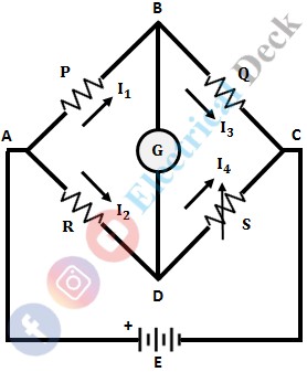
The below shows the circuit connections of Wheatstone Bridge. It consists of four arms in which four resistances are connected (one in each arm). A source emf and null detector (galvanometer) are connected between points AC and BD respectively.

The arms with resistances R 1 and R 2 are called ratio arms. The resistance R 3 is the standard arm resistance and R 4 is the unknown resistance to be measured.
Working of Wheatstone Bridge :
The principle of working of Wheatstone Bridge is on the null deflection or null indication i.e., when the bridge is balanced the ratio of their resistances are equal and no current flows through the galvanometer.
If the bridge is unbalanced there will be a potential difference between B and D, which causes a current to flow through the galvanometer. In order to achieve a balanced condition, the known resistance and variable resistance should be varied. The basic circuit of the Wheatstone bridge is shown below.

let, P = Resistance of arm AB Q = Resistance of BC R = Resistance of AD S = Resistance of CD E = Source (battery) G = Galvanometer (detector).
The bridge is said to be balanced, when the potential difference between points A and B is equal to the voltage across points A and D (i.e., the potential difference across the galvanometer or BD is zero). Hence, no current flows through the galvanometer, thus the no deflection in it (null-deflection).

Under balancing condition, the voltage across AB will equal to the voltage across AD i.e., I 1 P = I 2 R ...(1) When the bridge is balanced, the following conditions also exist, Where E is the emf of the source. Substituting the values of I 1 and I 2 in equation 1, we get, Where, R = Unknown resistance S = Standard arm resistance P, Q = Ratio arms.
The above expression is the equation of the Wheatstone bridge under balanced condition. Hence, from the above equation, the value of unknown resistance R can be determined if the resistances in the other three arms i.e., P, Q, and S are known.
Sensitivity of the Wheatstone Bridge :
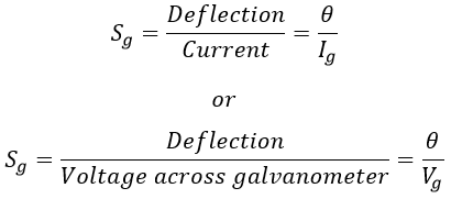
At the balance condition, the galvanometer reads zero current. But it deflects for a small unbalance in the bridge i.e., the deflection of the galvanometer depends on its sensitivity, which is given as,

Assume, θ = Deflection of the galvanometer I g = Current through the galvanometer V g = Voltage across the galvanometer.
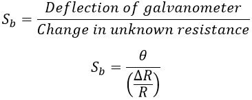
Sensitivity of the bridge is defined as the ratio of deflection of the galvanometer to the unit fractional change in the unknown resistance i.e.,

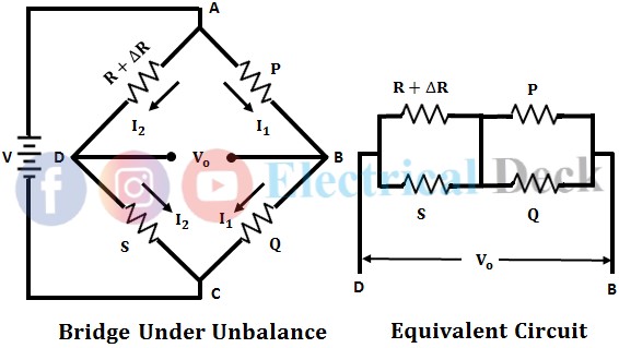
In order to obtain the sensitivity of the bridge, assuming a small unbalance in the bridge i.e., the unbalance ΔR is at resistance R. Due to this unbalance in the bridge, an emf V o appears across BD i.e., across the galvanometer as shown below.

Using Thevenin's method to determine the voltage, the voltage across the galvanometer or terminals BD is given as, Deflection of the galvanometer is given as, Therefore, the sensitivity of the bridge is,
Errors in wheatstone bridge :, the following factors should be taken into consideration in the precision measurement of medium resistances with the wheatstone bridge. resistance of connecting leads - a 25cm length connecting lead of 22 swg wire has a resistance of about 0.012ω and this represents more than 1 part in 1000 for a 10ω resistance. thermoelectric effects - the galvanometer deflection is affected by the thermoelectric emf's which are present in the measuring circuit due to the unbalance of the bridge. the thermoelectric effect can be minimized (or) eliminated by reversing the battery connections through a quick acting switch and adjusting the galvanometer until no change in the deflection is observed. the results are obtained by taking an average of the two readings. in this way, the thermoelectric effect may be eliminated. temperature effects - an increase in temperature is accompanied by a rise in resistance of all copper and aluminum parts. the errors caused by a change of resistance due to the change of temperature produces serious errors in measurements. in case of copper which has a temperature coefficient of 0.004%c, a change in temperature of 33.8° f will cause an error of 0.4%. contact resistance - the errors in the measurement is also occurred due to contact resistances of switches. a dial may have a contact resistance of about 0.003ω and thus a four dial resistance box has a contact resistance of about 0.012ω. this value is high, especially in the measurement of low resistances. this can be overcome by using kelvin's bridge for precision resistance measurements., limitations of wheat stone bridge :, the heating effect caused by the current flowing through the resistors results in the change of resistance of the bridge arms. this can be checked if the dissipation of power in the bridge arms is calculated in advance. this ensures the restriction of current to a safe value and thus mitigates the heating effect. while using wheatstone's bridge for the measurement of low resistance, the load and contact resistances become more significant which introduces error. in order to eliminate this drawback, kelvin's double bridge is employed. in case of high resistance measurements, the galvanometer fails to indicate the imbalance in the bridge. this is because the resistance of the bridge becomes so high that the galvanometer becomes insensitive to the imbalance. this can be avoided by replacing the battery by means of a power supply and the galvanometer with a dc vtvm (vacuum tube voltmeter). however, measurement of resistances in the range of megaohms is never possible with a wheatstone bridge., applications of wheat stone bridge :, a precise measurement of low resistance can be done with wheatstone's bridge. to locate the cable fault in telephone companies. the wheatstone bridge configuration can be used with electrical sensors like strain gauge, ldr, and a thermistor to measure strain, light, and temperature. it can also be used to measure capacitance and inductance..
Do not enter any spam links and messages
Contact Form

IMAGES
COMMENTS
In a Wheatstone's bridge, the resistance in the three arms are P, Q, R, and its fourth arm has a parallel combination of two resistances S 1 and S 2, The balancing condition of the bridge is _____ Constantan wire is used for making standard resistance, because it has ______.
Experiment 3 Bridge Circuits 1 Motivation This experiment explores using a DC Wheatstone Bridge to make precise resistance measurements. The lab equipment permits resistance measurements that have an accuracy of ≈0.5%. You will also use an AC Wheatstone Bridge to make an inductance measurement. You will employ error
remove this source of error, swap your unknown and your decade resistance box and repeat your experiment. Note: when swapping X and R you are also using opposite wire lengths. Now the length of wire related to X is (100-L) instead of L. That is why you have the two different equations for X depending on if it is on the left or the right.
May 30, 2021 · Errors in Wheatstone Bridge : The following factors should be taken into consideration in the precision measurement of medium resistances with the Wheatstone bridge. Resistance of Connecting Leads - A 25cm length connecting lead of 22 SWG wire has a resistance of about 0.012Ω and this represents more than 1 part in 1000 for a 10Ω resistance.
EXPERIMENT 1 - EE 2101 Lab4 - Wheatstone Bridge.pdf Author: hasnerk Created Date: 8/18/2021 10:00:22 AM ...
You can also do step 1 in both the Wheatstone Bridge and AC Bridge sections. THE WHEATSTONE BRIDGE The Wheatstone Bridge circuit can be used to measure an unknown resistance in terms of three known resistances by adjusting one or more of the known resistors to obtain a zero signal (i.e. a “null” reading) on a meter.
The main advantage of the slide wire form of Wheatstone Bridge is that it requires only one standard resistor, R2. In addition, its open design allows the student to see exactly how it works. The box form of bridge, on the other hand, is more accurate and quite portable. II. LABORATORY PROCEDURE 1.
Experiment Three 3.1 Measure of Resistance using a Wheatstone Bridge Circuit. As showing in the figure 3.1.1 the basic Wheatstone Bridge circuit is formed by four resistances and a galvanometer or very sensitive voltmeter centered in zero and connected to a source of DC. Figure 3.1.1 R 1 and R 2 are fixed resistances of a well-known value. R 3
resistance arms forming a closed circuit, with a dc source of current applied to two opposite junctions and a current detector connected to the other two junctions. Wheatstone‟s bridge is used for accurate measurement of resistance. The circuit diagram of a typical Wheatstone‟s bridge is given in fig. 1.1 Fig 1.1 Wheatstone Bridge
FIG. 2. Wheatstone bridge set-up for the experiment. 1. Set up the Wheatstone circuit in the –gure. Note that the portion of the slider wire labelled L. L. is on the side of the set-up with the unknown resistance R. 2. Select a resistor (R in the –gure) to analyze; color decode its resistance and record this value. 3. Set the R. 0