- PRO Courses Guides New Tech Help Pro Expert Videos About wikiHow Pro Upgrade Sign In
- EDIT Edit this Article
- EXPLORE Tech Help Pro About Us Random Article Quizzes Request a New Article Community Dashboard This Or That Game Forums Popular Categories Arts and Entertainment Artwork Books Movies Computers and Electronics Computers Phone Skills Technology Hacks Health Men's Health Mental Health Women's Health Relationships Dating Love Relationship Issues Hobbies and Crafts Crafts Drawing Games Education & Communication Communication Skills Personal Development Studying Personal Care and Style Fashion Hair Care Personal Hygiene Youth Personal Care School Stuff Dating All Categories Arts and Entertainment Finance and Business Home and Garden Relationship Quizzes Cars & Other Vehicles Food and Entertaining Personal Care and Style Sports and Fitness Computers and Electronics Health Pets and Animals Travel Education & Communication Hobbies and Crafts Philosophy and Religion Work World Family Life Holidays and Traditions Relationships Youth
- Browse Articles
- Learn Something New
- Quizzes Hot
- Happiness Hub
- This Or That Game
- Train Your Brain
- Explore More
- Support wikiHow
- About wikiHow
- Log in / Sign up
- Education and Communications
- Electromagnetism

How to Solve a Series Circuit
Last Updated: June 8, 2024
This article was co-authored by Ralph Childers . Ralph Childers is a master electrician based in the Portland, Oregon area with over 30 years of conducting and teaching electrical work. Ralph received his B.S. in Electrical Engineering from the University of Louisiana at Lafayette and holds an Oregon Journeyman Electrical License as well as electrician licenses in Louisiana and Texas. This article has been viewed 304,696 times.
A series circuit is the simplest type of circuit: a single loop with no branching paths. The electrical charge leaves the positive terminal of the power supply, passes through each resistor or other components in turn, then returns to the negative terminal. The properties of series circuits are not hard to learn, but it can take some thinking to figure out how to use them.
Resistance, Voltage, and Current

- If you know any two of these values, use Ohm's Law to solve for the third. For example, if you know the resistance and voltage of a circuit, rearrange V = IR to I = V / R, and plug in the known values to solve for I, the current.
- Always use values form the same part of the circuit. If you are trying to solve for the resistance of a single resistor, you will need to know the voltage and current for that resistor. Do not use the voltage for the whole circuit.

- On a circuit diagram, a resistor looks like a zig-zag in the wire.

- Old-fashioned textbooks may use E to represent voltage instead of V. You may also see ΔV, meaning "change in voltage." The symbol Δ is the Greek letter delta, and means "change."

- Example 3: A series circuit plugged into a 220V source is connected to several light bulbs. You measure the voltage drop across a light bulb with resistance 100 Ω and get a result of 80V. How much current flows through this circuit? You know the values of V and R for the light bulb, so you can use Ohm's Law to solve for the current: I = 80V / 100Ω = 0.8 A (amps) Because the current is the same anywhere on a series circuit, the answer is 0.8 amps. Be careful: you cannot use the circuit's total voltage drop 220V. Ohm's Law only works if you use values for the same portion of the circuit, and this problem does not tell you the total resistance of the circuit.

- Fill out the chart with all values provided in the problem.

Power and Energy

- In the classroom, however, you do not need to find the power and energy unless the problem asks you to. If the problem only tells you to fill out a circuit diagram, use the method above to find resistance, voltage, and current.

- All the formulas in this section work for the circuit as a whole, or for individual components. Just make sure to use quantities that refer to the same portion of the circuit.

- The equations above give you a power result in watts. Multiply by seconds to get an energy result in Joules.
Expert Q&A
- If the internal resistance of the Power source was given (r), Then add it to the total resistance of the circuit (V=I*(R+r)) Thanks Helpful 0 Not Helpful 0
- Total voltage of circuit = sum of the voltages of all resistors connected in series. Thanks Helpful 0 Not Helpful 0

- Do not rely on these approaches for a parallel circuit, where the wire divides into two or more branches. Ohm's Law still applies to those, but many of the other formulas do not. Thanks Helpful 3 Not Helpful 0
You Might Also Like

- ↑ http://www.physicsclassroom.com/class/circuits/Lesson-4/Series-Circuits
- ↑ http://farside.ph.utexas.edu/teaching/302l/lectures/node57.html
- ↑ http://www.physicsclassroom.com/calcpad/circuits
About This Article

- Send fan mail to authors
Reader Success Stories
Laone Moipolai
Jun 10, 2021
Did this article help you?

Chaman Chauhan
May 4, 2017
Jun 18, 2022

Featured Articles

Trending Articles

Watch Articles

- Terms of Use
- Privacy Policy
- Do Not Sell or Share My Info
- Not Selling Info
Get all the best how-tos!
Sign up for wikiHow's weekly email newsletter

StickMan Physics
Animated Physics Lessons
Series Circuit
Series circuits.
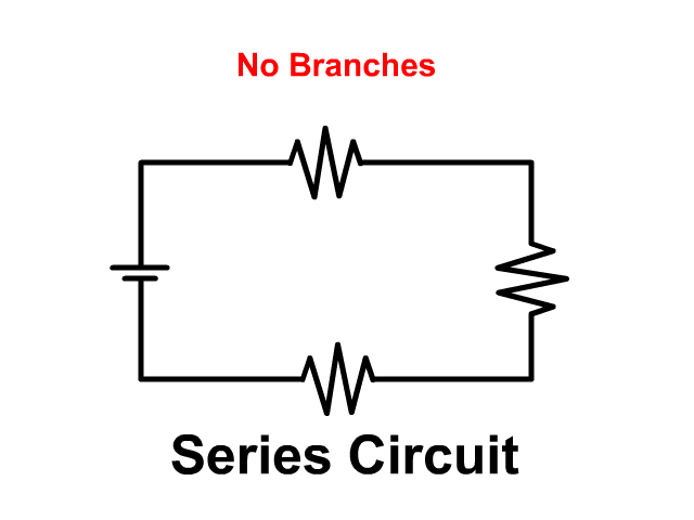
In a series circuit components like resistors and loads are connected in a single path. Current must go through every component in order starting from the positive terminal of the battery through everything in order and back to the negative battery terminal.
Series Circuit Handout to go along with the problems on this page and the PhET lab at the end.
- Practice and Series Circuit Virtual Lab Sheet
Series Circuits vs. Parallel Circuits
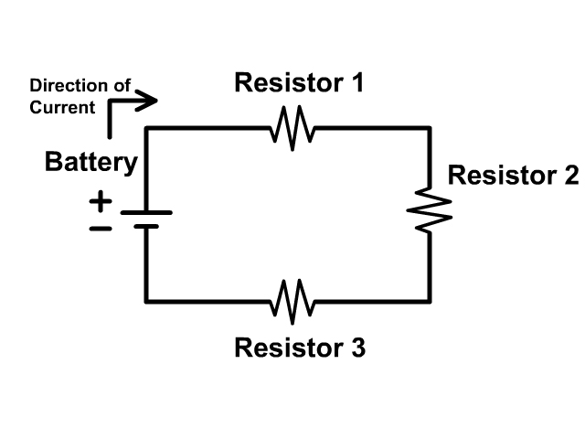
Series Circuits only have one path while parallel circuits we will see in a later unit have branches. Compare the pictures below each with three resistors.
Lights in a Series Circuit Compared to a Parallel Circuit
When lights are connected in a series circuit and one goes out the circuit becomes open and no other light works. This is because there is no path to the negative terminal of the battery when a circuit is open.
When lights are connected in parallel circuit and one light goes out the remaining ones stay on. No current will flow down the branch with the disconnected light bulb since that branch is open. Current will follow the other paths to the negative terminal of the battery leaving the other lights on.
Series Circuit Diagrams
To keep the models simple we will only places a battery and resistors in the circuits of our diagrams on this page. Remember that the longer line in the battery symbol is the positive terminal and the shorter line is the negative terminal. The convention is to have current run from the positive terminal to the negative terminal. Due to this convention the resistors are numbered in order. Here the resistors get their number resistor 1, resistor 2, and resistor 3 based on the flow of current starting from the positive terminal of the battery.
Series Circuit Rules
Voltage drop in a series circuit.
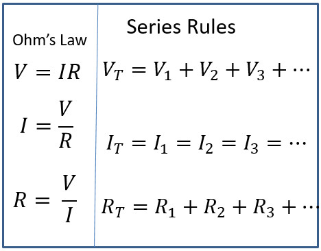
In a series circuit voltage drops across each resistor until the entire amount provided by the battery has dropped. If you add all the individual voltage drops of a series circuit together you can determine the voltage of the entire circuit (V T ) found at the power source.
V T = V 1 + V 2 + V 3 + …
Current in a Series Circuit
There is only one path in a series circuit for current to travel on. All current must run from the positive terminal to the negative terminal of the power source. Observe the animation of how the same current has to flow through every component of the circuit in series.
I T = I 1 = I 2 = I 3 = …
Resistance in a Series Circuit
Any resistor or load (device with a resistance) in a series acts like a speed bump in a series slowing current down . Since there is only one conductive path in series every device adds to total resistance.
R T = R 1 + R 2 + R 3 + …
Note that a wire itself has resistance and the less conductive a wire is the more resistance it would add to a circuit. We will ignore this in our examples below for simplicity and pretend the wire was 100% conductive.
Circuit Equations
Ohm's Law (V=IR) , Voltage equals current times resistance, can be used anywhere in the circuit but only at a single location.
See all the squares in red above, if you are using Ohm's law you can only use information in that location, the V,I, and R within a single square .
The location can be an individual resistor, for example resistor one with the variables Voltage (V 1 ), Current (I 1 ), Resistance (R 1 ). The location can also be at the battery, which is a measure that represents the overall circuits voltage (V T ), current (I T ), and Resistance (R T ).
At the battery the subscript T (ex. V T ) stands for total or of the circuit. Some equations sheets may use emf (ex. V emf ) or another notation, if there is any subscript other than a number it will likely be of the circuit.
When you are using information between different red blocks you must use the series circuit rules .
Start any problem by drawing out the circuit and have every resistor labeled as you see in the picture above. Then write in all your givens. Next, follow the basic steps to a series circuit problem.
Basic Steps To A Series Circuit Problem
#1 See if you can do Ohm's Law (V=IR) at any location in the circuit.
#2 See if you have current anywhere because that current will be the same everywhere following the series circuit rule below.
#3 Check if you can do any of the other series circuit rules.
You will continue to follow these steps over and over until everything in the circuit is complete. Follow our examples below until you feel comfortable to follow the steps solving series circuit problems on your own.
Example Problem 1
Example 1 Step 1
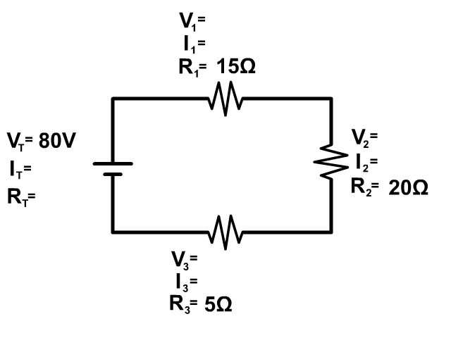
Here we don't have enough information to use Ohm's Law (V=IR) at any location so we need to look at the series circuit equations
We can use the last of the equations to solve for the resistance of the circuit (at the battery first). We only have three resistors so we leave off any other part not in this circuit from the equation
R T = R 1 + R 2 + R 3
R T = 15Ω + 20Ω + 5Ω = 40Ω
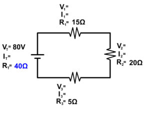
Example 1 Step 2
Now we have enough information to use Ohm's law at the battery to determine the current (I T ) at the battery
I T =V T /R T
I T =80V/40Ω = 2A
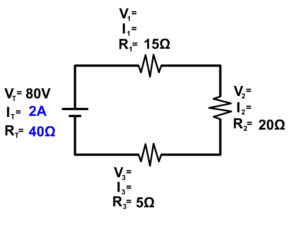
Example 1 Step 3
Now that we know current at any location, in this case the battery, we know it everywhere in a series circuit
I T = I 1 = I 2 = I 3
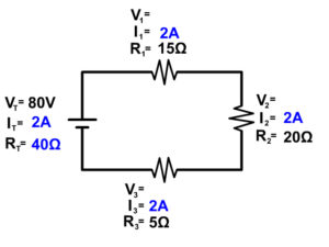
Example 1 Step 4
Now we have enough information to solve for voltage everywhere using Ohm's Law (V=IR)
V 1 = I 1 x R 1
V 1 = 2A x 15Ω = 30V
V 2 = I 2 x R 2
V 2 = 2A x 20Ω = 40 V
V 3 = I 3 x R 3
V 3 = 2A x 5Ω = 10 V
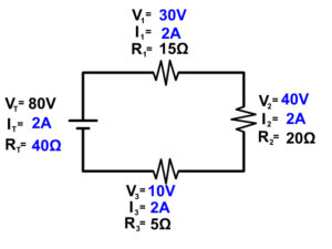
It is important to make one final check. Since we finished using Ohm's Law to solve for V 3 , lets make sure this last step also fits with the series circuit rule.
V T = V 1 + V 2 + V 3
80V = 30V + 40V + 10V
This is also mathematically correct so we know we solved for all the parts of this circuit correctly. If it did not we would know we had an error and would have to trace back our steps or starting over is sometimes easier.
Example Problem 2
Note: While our example stick to whole numbers for simplicity, this would be very uncommon and you would normally have decimals . Do not be shocked if you have decimals , just make sure all the rules are followed and do a final check as presented in the examples below.
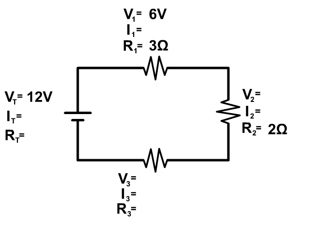
Example 2 Step 1
You have enough information to start this circuit at the first resistor using Ohm's Law (V=IR)
V 1 = I 1 x R 1 rearranges to I 1 = V 1 /R 1 when solving for current.
I 1 = 6V/3Ω = 2A
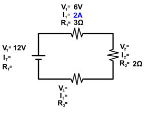
Example 2 Step 2
Now that we know current at the at one location, the first resistor, we know it's the same everywhere following series circuit rules.
2A = 2A = 2A = 2A
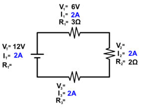
Example 2 Step 3
Now we have enough information to use Ohm's Law (V=IR) to solve for resistance of the circuit (at the battery) and voltage at resistor 2
V T = I T x R T rearranges to R T = V T /I T
R T = V T /I T
R T = 12V/2A = 6Ω
V 2 = 2A x 2Ω = 4V
Now our circuit looks like this
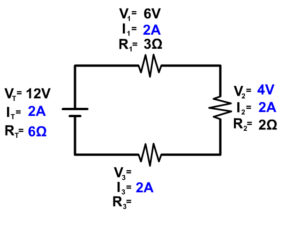
Example 2 Step 4
From here we can solve for either voltage or resistance of resistor 3 using the overall series circuit rules.
12V = 6V + 4V + V 3
V 3 = 12V - 6V - 4V
6Ω = 3Ω + 2Ω + R 3
R 3 = 6Ω - 3Ω - 2Ω
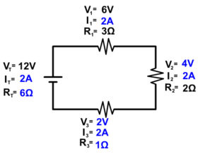
Since we solved for R 3 last using series circuit rules do the final check at resistor three making sure it follows Ohm's Law at this location as well.
2V = 2A x 1Ω
It makes the final check so we know we solved for the parts of this circuit correctly.
Example Problem 3
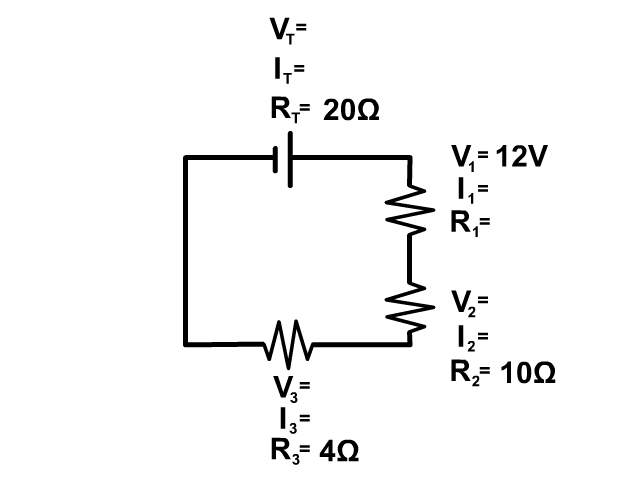
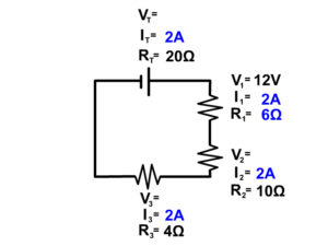
Example 3 Step 1
In this circuit we don't have enough information to start with Ohm's Law since we don't have two out of three parts of Ohm's Law at any one location.
We do have enough information to start with the series circuit resistor rule. R T = R 1 + R 2 + R 3
20Ω = R 1 + 10Ω + 4Ω
R 1 = 20Ω - 10Ω - 4Ω = 6Ω
Our circuit now looks like this
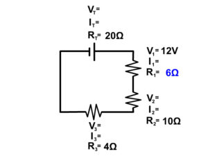
Example 3 Step 2
Now we can solve for current at resistor 1 using Ohm's Law
I 1 = V 1 /R 1
I 1 = 12V/6Ω = 2A
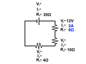
Example 3 Step 3
Now that we know current in one location we know the current everywhere in the circuit following the series circuit rules.
Example 3 Step 4
Now use Ohm's Law (V=IR) to solve for all the remaining components since we have enough information to do so.
V T = I T x R T
V T = 2A x 20Ω = 40V
V 2 = 2A x 10Ω = 20V
V 3 = 2A x 4Ω = 8V
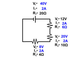
Since we ended by solving for V 3 using Ohm's Law, our final check is to make sure voltage also follow the series circuit rules for voltage.
40V = 12V + 20V + 8V
This is a correct mathematical statement so we know we solved our series circuit correctly.
Notice the following about some series circuit problems
Some problems as the one seen below are drawn showing multimeters taking the reading of the current as seen below. This is not part of the circuit and is just taking a reading.
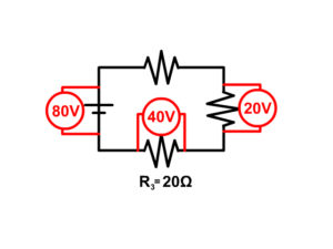
You would rewrite the problem above taking out the multimeters and placing the readings into the problem and start the problem as seen in example 4 below.
Example Problem 4
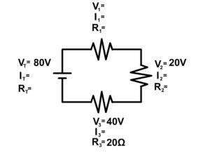
Try example 4 on your own and click "See Solution" to check your answers.
See Solution
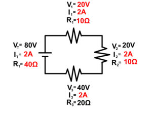
Another Way Current Can Be Given In A Series Circuit Problem
Be aware that current can also be drawn into a problem in the wire and not at a single resistor. This is not an additional resistor but seeing the current drawn as a circle over the wire shows you the current in that wire. Since there is only one wire going from the previous resistor to the new resistor, you know in series both of those must have that current as well. See the picture to see a visual of this.
Circuit Construction Kit
The following PhET circuit construction kit can help you understand the workings of circuits more.
CLICK HERE FOR THE SERIES CIRCUIT LAB SHEET
Go to the following website is the embedded version is not working
https://phet.colorado.edu/sims/html/circuit-construction-kit-dc/latest/circuit-construction-kit-dc_en.html
- Continue to Parallel Circuits
- Back to the Main Current and Circuits Page
- Back to the Stickman Physics Home Page
- Equation Sheet
Terms and Conditions - Privacy Policy
Series Parallel Circuit | Series Parallel Circuit Examples
What is a series-parallel circuit.
Not all circuits are simple series or parallel arrangements. Many are combinations of parallel resistors connected in series with other resistors or combined with other parallel groups. These can be described as a series-parallel circuit.
The simplest approach to analyzing a series-parallel circuit is to resolve each purely series group into its single equivalent resistance and to resolve each parallel group of resistors into its equivalent resistance. The process is repeated as many times as necessary.
As in all types of circuits, open-circuit and short-circuit conditions affect the currents and voltage drops throughout the circuit.
Series-Parallel Resistor Circuits
Simple Series-Parallel Circuit
Series-Parallel resistor circuits consist of combinations of series-connected and parallel-connected resistors. Figure 1 shows a circuit diagram of a very simple three-resistor series-parallel circuit. Resistors R 2 and R 3 are seen to be connected in parallel, and resistor R 1 is in series with the parallel combinations of R 2 and R 3 . The circuit current s vary from branch to branch, and the component voltage drops depend on the branch currents and on the component resistances. The supply current depends on the supply voltage and on the circuit resistance offered to the voltage source. Kirchhoff’s voltage and current laws are applied for analyzing series-parallel circuits.
Figure 1 : Circuit Diagram of Series-Parallel Circuit
Series-Parallel Equivalent Circuits
In the circuit shown in figure 2 (a), resistors R 2 and R 2 are in parallel, and together they are in series with R 1 . The level of current taken from the supply is easily calculated if R 2 and R 3 are first replaced with their equivalent resistance (R 2 ||R 3 ) as illustrated in figure 2(b). The circuit now becomes a simple two-resistor series circuit.
Figure 2 : Series-Parallel Circuit and Equivalent Circuit
- You May Also Read: Series Circuit Definition & Series Circuit Examples

Series-Parallel Circuit Example 1
Calculate the current drawn from the supply in the circuit shown in figure 2 (a).
Draw the equivalent circuit as in figure 2 (b) with
${{R}_{eq}}={{R}_{2}}||{{R}_{3}}$
To compute equivalent resistance:
\[{{R}_{eq}}=\frac{{{R}_{2}}*{{R}_{3}}}{{{R}_{2}}+{{R}_{3}}}=\frac{20*30}{20+30}=12\Omega \]
\[I=\frac{E}{{{R}_{1}}+{{R}_{eq}}}=\frac{25}{38+12}=0.5A\]
In figure 3 (a), another series-parallel resistor combination is shown. In this case, the circuit is reduced to a simple parallel circuit when R 2 and R 3 are replaced by their equivalent resistance. [See Figure 3(b)]
Figure 3 : Series-Parallel Circuit and its Equivalent Circuit
- You May Also Read: Parallel Circuit Definition & Parallel Circuit Examples
Series-Parallel Circuit Example 2
Determine the level of the supply current for the circuit shown in figure 3 (a).
Draw the equivalent circuit as in figure 3(b).
${{R}_{eq}}={{R}_{2}}+{{R}_{3}}=35+40=75\Omega $
R 1 and R eq are in parallel:
$R={{R}_{1}}||{{R}_{eq}}$
\[R=\frac{{{R}_{1}}*{{R}_{eq}}}{{{R}_{1}}+{{R}_{eq}}}=\frac{50*75}{50+75}=30\Omega \]
\[I=\frac{E}{R}=\frac{75}{30}=2.5A\]
Current in Series-Parallel Circuit
The circuit of figure 2 (a) is reproduced in figure 4 with the branch currents and voltages identified. It is seen that the supply current flows through resistor R 1 and that it splits up into I 2 and I 3 in order to flow through R 2 and R 3 . Returning to the supply negative terminal, the current is once again I. it is seen that
$I={{I}_{2}}+{{I}_{3}}$
Figure 4: Current and Voltage in Series-Parallel Circuit
Similarly, the supply current splits up between the resistors in figure 5, which is a reproduction of a circuit shown in figure 3 (a). Here I 1 flows through R 1 , and I 2 flows through R 2 and R 3 , and the supply current is
$I={{I}_{1}}+{{I}_{2}}$
Figure 5: Currents and Voltages in Series-Parallel Circuit
In each of these cases, the current through the individual resistors can be calculated easily using current-divider rule.
Voltage Drops in Series-Parallel Circuit
As always, the voltage drop across any resistor is the product of the resistance value and the current through the resistor. In figure 4,
${{V}_{1}}=I{{R}_{1}}$
${{V}_{2}}={{I}_{2}}{{R}_{2}}={{V}_{3}}={{I}_{3}}{{R}_{3}}$
$E={{V}_{1}}+{{V}_{2}}$
Similarly, in figure 5,
${{V}_{1}}={{I}_{1}}{{R}_{1}}$
${{V}_{2}}={{I}_{2}}{{R}_{2}}$
${{V}_{3}}={{I}_{2}}{{R}_{3}}$
$E={{V}_{1}}={{V}_{2}}+{{V}_{3}}$
Series-Parallel Circuit Example 3
Using the voltage divider theorem, analyze the circuit in figure (a) below to determine the resistor voltage drops and the branch currents.
Figure. Series-Parallel Circuit Example
\[{{R}_{eq}}={{R}_{2}}||{{R}_{3}}\]
For voltage divider R 1 and R eq , as shown in figure (b) above:
\[{{V}_{2}}=E*\frac{{{R}_{eq}}}{{{R}_{1}}+{{R}_{eq}}}=25*\frac{12}{38+12}=6V\]
\[{{V}_{1}}=E*\frac{{{R}_{1}}}{{{R}_{1}}+{{R}_{eq}}}=25*\frac{38}{38+12}=19V\]
For branch currents:
\[I=\frac{{{V}_{1}}}{{{R}_{1}}}=\frac{19}{38}=0.5A\]
\[{{I}_{2}}=\frac{{{V}_{2}}}{{{R}_{2}}}=\frac{6}{20}=0.3A\]
\[{{I}_{3}}=\frac{{{V}_{3}}}{{{R}_{3}}}=\frac{6}{30}=0.2A\]
Series-Parallel Circuit Formula
The formula for calculating the total resistance (R T ) in a series-parallel circuit depends on the arrangement of resistors. Here are the formulas for common series-parallel circuit configurations:
- Resistors in Series : R T = R 1 + R 2 + R 3 + … + R n
- Resistors in Parallel : 1/R T = 1/R 1 + 1/R 2 + 1/R 3 + … + 1/R n
- Series-Parallel Combination : To calculate the total resistance in a complex series-parallel circuit, first simplify the circuit by identifying series and parallel sections. Then use the formulas for resistors in series and parallel to find the equivalent resistance of each section. Finally, combine the equivalent resistances to determine the total resistance of the circuit.
Open-Circuit and Short-circuit in a Series-Parallel Circuit
The effect of an open-circuit or short-circuit condition on a series-parallel circuit depends on just where in the circuit the fault occurs. Consider figure 6, where an open-circuit is shown at the end of R 1 . This has the same effect as an open-circuit in the supply line so that all current levels are zero. Also, because the currents are zero, there are no voltage drops across resistors, and consequently all of the supply voltage E appears across the open-circuit.
Figure 6: Open-Circuit at Resistor R 1
An open-circuit in one branch of a series-parallel circuit usually alters the current levels in several branches of the circuit.
In the case of an open-circuit at one end of the parallel resistors, as shown in figure 7, I 2 goes to zero. The current through R 1 and R 2 is now equal to the supply current and is calculated as
\[I=\frac{E}{{{R}_{1}}+{{R}_{2}}}\]
Also, because there is no current through R 3 , there is no voltage drop across it, and the voltage at the open circuit is equal to V 2 .
Figure 7: Open-Circuit at Resistor R 3
For the short circuit condition shown in figure 8, the resistance between the terminals of R 1 is effectively zero. Therefore, the supply voltage appears across R 2 and R 3 in parallel. This gives a supply current of
\[I=\frac{E}{{{R}_{2}}||{{R}_{3}}}\]
And the branch currents are
\[{{I}_{2}}=\frac{E}{{{R}_{2}}}\]
\[{{I}_{3}}=\frac{E}{{{R}_{3}}}\]
It is seen that the levels of current through R 2 and R 3 have been increased from the normal (before the short-circuit) condition. This could cause excessive power dissipation in the components if they have previously been operating near their maximum rating.
Fig.8: Short-Circuit Across Resistor R 1
A short-circuit in one branch of a series-parallel circuit usually alters the current levels in several branches of the circuit.
The short-circuit condition illustrated in figure 9 effectively reduces I 2 and I 3 to zero and increases the supply current to
\[I=\frac{E}{{{R}_{1}}}\]
Obviously, the current through R 1 is now greater than normal, and again power dissipation might present a problem.
Fig.9: Short-Circuit Across Resistor R 3
Analyzing a Series-Parallel Circuit
Analysis procedure for series-parallel resistor circuits is as follow:
- Draw a circuit diagram identifying all components by number and showing all currents and resistor voltage drops.
- Convert all series branches of two or more resistors into a single equivalent resistance.
- Convert all parallel combinations of two or more resistors into a single equivalent resistance.
- Repeat procedures 2 and 3 until the desired level of simplification is achieved.
The final circuit should be straightforward series or parallel circuit, which can be analyzed in the normal way. Once the current through each equivalent resistance, or the voltage across it, is known, the original circuit can be used to determine individual resistor currents and voltages.
Key Takeaways on Series-Parallel Circuit
- Series-parallel circuits combine both series and parallel connections of electrical components.
- They offer flexibility in designing complex electrical systems, allowing for different voltage levels, current paths, and component configurations.
- Total resistance in a series-parallel circuit is calculated by considering resistances in both series and parallel sections.
- Current remains the same throughout components connected in series, while in parallel branches, the total current is divided based on resistance values.
- Different resistor values can be used in a series-parallel circuit, providing flexibility in adjusting total resistance and current distribution.
- Voltage is divided among parallel branches, while the voltage across components connected in series adds up to the total voltage.
- Power dissipation occurs independently in each component, and it can be calculated using the formula P = I^2 * R.
- Different types of components like resistors, capacitors, and inductors can be combined in a series-parallel circuit, considering their electrical properties and compatibility.
- Series-parallel circuits are commonly used in power distribution networks, battery banks, audio systems, lighting circuits, and electronic devices.
- Troubleshooting issues in a series-parallel circuit involves measuring voltage and current, checking connections, testing components, and analyzing the circuit configuration. Safety precautions and appropriate tools should be used.
Series-Parallel Circuit FAQs
What is a series-parallel circuit?
A series-parallel circuit is a combination of both series and parallel connections of electrical components. It consists of multiple branches, where some components are connected in series within each branch, and these branches are then connected in parallel.
What are the advantages of using a series-parallel circuit?
Series-parallel circuits offer flexibility in designing complex electrical systems. They allow for a combination of different voltage levels, current paths, and component configurations. This flexibility makes them suitable for various applications, including power distribution networks and electronic devices.
How do I calculate the total resistance in a series-parallel circuit?
To calculate the total resistance in a series-parallel circuit, you need to consider the resistances in both the series and parallel sections. For the series portion, simply add up the resistances. For the parallel portion, you need to use the reciprocal of the sum of the reciprocals of individual resistances.
How does current flow in a series-parallel circuit?
In a series-parallel circuit, the current remains the same throughout the components connected in series. However, in the parallel branches, the total current is divided among the branches based on the resistance values. Each parallel branch allows current to flow independently.
Can I use different resistor values in a series-parallel circuit?
Yes, you can use different resistor values in a series-parallel circuit. The different resistor values provide flexibility in adjusting the total resistance and current distribution. It is important to consider the individual resistor values and their impact on the overall circuit performance.
How does voltage behave in a series-parallel circuit?
In a series-parallel circuit, the total voltage is divided among the parallel branches. The voltage across components connected in series adds up to the total voltage. This characteristic allows for different voltage levels in various parts of the circuit.
How does the power dissipation occur in a series-parallel circuit?
The power dissipation in a series-parallel circuit occurs independently in each component. The power dissipated in resistors can be calculated using the formula P = I^2 * R, where I is the current flowing through the resistor and R is the resistance value.
Can I combine different types of components in a series-parallel circuit?
Yes, you can combine different types of components, such as resistors, capacitors, and inductors, in a series-parallel circuit. However, it is essential to consider the electrical properties and characteristics of each component to ensure compatibility and proper circuit operation.
What are some common applications of series-parallel circuits?
Series-parallel circuits find applications in various electrical and electronic systems. They are commonly used in power distribution networks, battery banks, audio systems, lighting circuits, and complex electronic devices like computers and smartphones.
JEE-IIT-NCERT Physics & Math
Resistors in parallel and in series circuits problems and solutions.
Problem #1

- R 2 and R 3 arranged in parallel,
- R 1 and R p arranged in series, then

- R 2 is in parallel with R 3
- R 4 is in parallel with R 5 ,
- R 1 , R 23 and R 45 the series combination, then

Post a Comment for "Resistors in Parallel and in Series Circuits Problems and Solutions"

APlus Physics YouTube Channel
Show Me The Physics Youtube Channel
Fill in the Blank Notes
H) Series and Parallel Circuits
Why is it a good idea to connect Christmas lights 'in parallel'?
Circuits - Flash
Circuits - HTML5 Series and Parallel
Show Me The Physics
Which kind of circuit do we have below?
1) Series Circuit - circuit that has only one current path

Dorling Kindersley Books
Ex 1) Ammeter – Meter that measures Current

Reference Table Equations
a) I T = I 1 = I 2 = I 3 = ...
Total Current coming from source = Current going through each resistor.
b) R T = R 1 + R 2 + R 3 + …
R T = 6.0 ohms
c) V T = V 1 + V 2 + V 3 + ……
d) V T = I T R T OR R T = V T / I T
Find total current (I T )
V T = I T R T
20. V = I T (6.0 ohms)
I T = 3.3 amps = I 1 = I 2
Name that Circuit
Show Me The Physics YouTube Channel
School blocks YouTube? Use the file below.
ConstructSeriesCircuit

©Tony Mangiacapre., - All Rights Reserved [ Home ] Established 1995 Use any material on this site (w/ attribution)

- Trending Categories

- Selected Reading
- UPSC IAS Exams Notes
- Developer's Best Practices
- Questions and Answers
- Effective Resume Writing
- HR Interview Questions
- Computer Glossary
Series RLC Circuit: Analysis and Example Problems
Consider the circuit consisting of R, L and C connected in series across a supply voltage of V (RMS) volts. The resulting current I (RMS) is flowing in the circuit. Since the R, L and C are connected in series, thus current is same through all the three elements. For the convenience of the analysis, the current can be taken as reference phasor. Therefore,
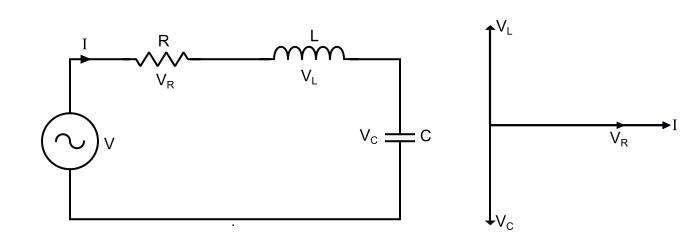
$$\mathrm{Voltage\:acorss\:\mathit{R},\mathit{V}_{R}=\mathit{IR}}$$
$$\mathrm{Voltage\:acorss\:\mathit{L},\mathit{V}_{L}=\mathit{IX}_{L}}$$
$$\mathrm{Voltage\:acorss\:\mathit{C},\mathit{V}_{C}=\mathit{IX}_{c}}$$
- X L = jωL = Inductive Reactince,
- X c = 1/jωC = Capacitive reactance.
- V R is in phase with I .
- V L is leading the current I by 90°.
- V C is lagging the I by 90°.
The total voltage is the phasor sum of V R , V L and V C , i.e.,
$$\mathrm{\mathit{V} = \mathit{V}_{R}+\mathit{V}_{L}+\mathit{V}_{C}}$$
$$\mathrm{Magnitude\:of\:voltage,|\mathit{V}|=\sqrt{\mathit{V}_{R}^{2}+(\mathit{V}_{L}-\mathit{V}_{C})^{2}}}$$
$$\mathrm{\Rightarrow\:|\mathit{V}|=\sqrt{(\mathit{IR})^{2}+(\mathit{IX}_{L}-\mathit{IX}_{C})^{2}}=I\sqrt{(R)^{2}+(X_{L}-X_{C})^{2}}}$$
$$\mathrm{Phase\:angle\:of\:voltage,\Phi=\tan^{-1}(\frac{V_{L}-V_{C}}{V_{R}})=\tan^{-1}(\frac{\mathit{X}_{L}-\mathit{X}_{C}}{R})}$$
$$\mathrm{Circuit\:current,\mathit{I}=\frac{|V|\angle\Phi}{\sqrt{(R)^{2}+(\mathit{X}_{L}-\mathit{X}_{C})^{2}}}}$$
Where, $(\sqrt{(\mathit{R})^{2}+(\mathit{X}_{L}-\mathit{X}_{C})^{2}})$ is the opposition offered to the current flow and is known as Impedance of the circuit. It is denoted by Z, thus,
$$\mathrm{\mathit{Z}=\mathit{R}+\mathit{X}_{L}+\mathit{X}_{C}=\mathit{R}+\mathit{j}(\omega L-\frac{1}{\omega C})}$$
$$\mathrm{Magnitude\:of\:impedance,|\mathit{Z}|=\sqrt{(\mathit{R})^{2}+(\mathit{X}_{L}-\mathit{X}_{C})^{2}}}$$
$$\mathrm{Impedance\:angle,\theta=\tan^{-1}(\frac{\mathit{X}_{L}-\mathit{X}_{C}}{\mathit{R}})}$$
Circuit Power Factor
The power of an AC circuit is defined as the ration of active power to the total power. i.e.
$$\mathrm{Power\:Factor,Cos\Phi=\frac{Active\:power}{Total\:Power}}$$
$$\mathrm{\Rightarrow\:Cos\Phi=\frac{\mathit{I}^{2}\mathit{R}}{\mathit{I}^{2}\mathit{Z}}=\frac{R}{Z}=\frac{\mathit{R}}{\sqrt{(\mathit{R})^{2}+(\mathit{X}_{L}-\mathit{X}_{C})^{2}}}}$$
Power Consumed
The power is consumed in the circuit only by the resistor, the inductor and capacitor does consume any power. Therefore,
$$\mathrm{\mathit{P}=VICos\Phi=(\mathit{IZ})×\mathit{I}×\frac{\mathit{R}}{Z}=\mathit{I}^{2}\mathit{R}}$$
Three cases of series RLC circuit
Case 1 – When X L > X C , i.e. (X L - X C ) is positive, thus, the phase angle φ is positive, so the circuit behaves as an inductive circuit and has lagging power factor.
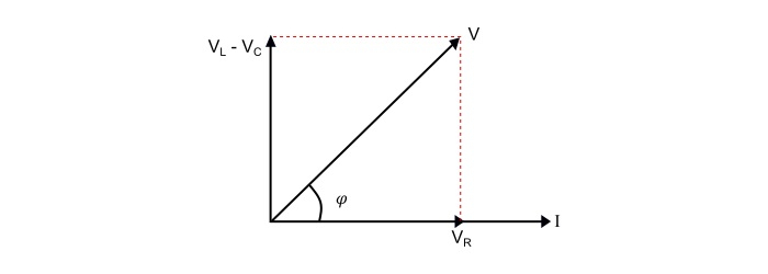
Case 2 – When X L < X C , i.e. (X L - X C ) is negative, thus, the phase angle φ is negative, so the circuit behaves as an inductive circuit and has lagging power factor.
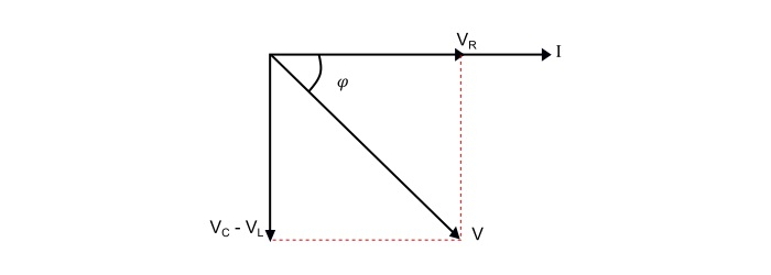
Case 3 – When X L = X C , i.e. (X L - X C ) is zero, thus, the phase angle φ is zero, so the circuit acts as a purely resistive circuit and has unity power factor.

Now, if the applied voltage is given by,
$$\mathrm{ u=\mathit{V}_{m}sin(\omega t)}$$
Then, the equation of the circuit current will be,
$$\mathrm{i=\mathit{I}_{m}sin(\omega t\:±\:\Phi)}$$
The value of φ will be positive or negative depending upon which reactance (X L or X C ) predominates.
Series Resonance
The resonance occurs in a series RLC circuit, when the reactive component of the impedance becomes zero, i.e.
$$\mathrm{(\mathit{X}_{L}-\mathit{X}_{C})=0}$$
$$\mathrm{\Rightarrow(\omega L-\frac{1}{\omega \mathit{C}})=0}$$
$$\mathrm{\Rightarrow\:\omega L=\frac{1}{\omega \mathit{C}}}$$
Therefore, the resonant frequency is
$$\mathrm{\omega_{0}=\frac{1}{\sqrt{\mathit{LC}}}}$$
Effects of series resonance
- X L = X C ,thus ω 0 = $1/ \sqrt{LC}$
- Z R = R = Minimum
- Circuit current at resonance, I r = V/R =Maximum.
- Circuit power factor is unity. Hence, circuit is purely resistive.
- The voltage across inductor and capacitor being equal, i.e. V L = V C .
Resonance Curve
The curve between current and frequency is known as resonance curve.
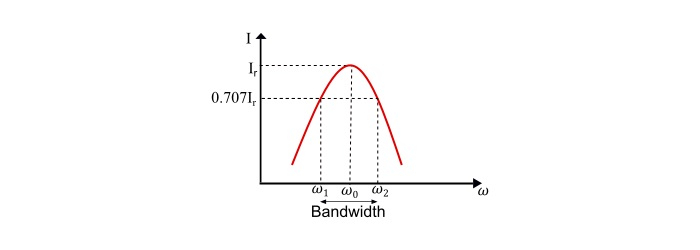
$$\mathrm{Lower\:Cut\:off\:frequency,\omega_{1}=-\frac{\mathit{R}}{2\mathit{L}}+\sqrt{(\frac{\mathit{R}}{2\mathit{L}})^{2}+\frac{1}{LC}}}$$
$$\mathrm{Upper\:Cut\:off\:frequency,\omega_{2}=\frac{\mathit{R}}{2L}+\sqrt{(\frac{\mathit{R}}{2\mathit{L}})^{2}+\frac{1}{\mathit{LC}}}}$$
Therefore, the bandwidth of the circuit is
$$\mathrm{BW=\omega_{2}-\omega_{1}=\frac{\mathit{R}}{\mathit{L}}}$$
Q – Factor of Series Resonant Circuit
The Q-factor (Quality Factor) of the circuit is defined as the ratio of reactive power to the active power, i.e.
$$\mathrm{\mathit{Q}-factor=\frac{Reactive Power}{Active Power}}$$
$$\mathrm{\Rightarrow\:\mathit{Q}-factor=\frac{I^{2}X_{L}}{I^{2}R}=\frac{I^{2}X_{c}}{I^{2}R}}$$
$$\mathrm{\Rightarrow\:\mathit{Q}-factor=\frac{\omega L}{R}=\frac{1}{\omega CR}}$$
At resonance,
$$\mathrm{\Rightarrow\:\mathit{Q}_{0}-factor=\frac{\omega_{0}L}{\mathit{R}}=\frac{\mathit{L}}{R\sqrt{\mathit{LC}}}=\frac{1}{\mathit{R}}\sqrt{\frac{\mathit{L}}{\mathit{C}}}}$$
Numerical Example
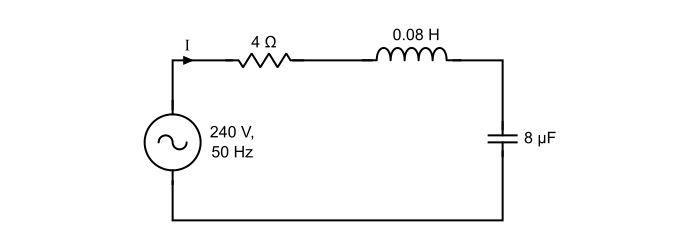
A 240 V, 50 Hz AC supply is applied a coil of 0.08 H inductance and 4 Ω resistance connected in series with a capacitor of 8 μF. Calculate the following −
- Circuit current,
- Phase angle between voltage and current,
- Power factor,
- Power consumed,
- Q-factor of the circuit at resonant frequency.
$$\mathrm{\mathit{X}_{L}=\omega L=2\pi \mathit{fL}=2\pi×50×0.08=25.12 Ω}$$
$$\mathrm{\mathit{X}_{C}=\frac{1}{\omega C}=\frac{1}{2\pi \mathit{fL}}=\frac{1}{2\pi×50×8×10^{−6}}=398.09\:Ω}$$
- Impedance of the circuit
$$\mathrm{Z=\sqrt{(\mathit{R})^{2}+(\mathit{X}_{L}-\mathit{X}_{C})^{2}}=\sqrt{(4)^{2}+(25.12−398.09)^{2}}=372.99\:Ω}$$
- Circuit current
$$\mathrm{\mathit{I}=\frac{\mathit{V}}{\mathit{Z}}=\frac{240}{372.99}=0.643\:A}$$
- Phase angle between voltage and current
$$\mathrm{\Phi=\tan^{-1}(\frac{X_{L}-X_{C}}{R})=\tan^{-1}(\frac{25.12-398.09}{4})=−89.38°}$$
The negative sing of phase angle shows that current is leading the voltage.
- Power Factor
$$\mathrm{cos\phi=\frac{R}{Z}=\frac{4}{372.99}=0.01072 (leading)}$$
- Power consumed
$$\mathrm{\mathit{P}=\mathit{VI}cos\Phi=240×0.643×0.01072=1.654\:W}$$
- Q-factor of circuit at series resonance
$$\mathrm{\mathit{Q}_{0}-\mathit{factor}=\frac{1}{\mathit{R}}\sqrt{\frac{\mathit{L}}{\mathit{C}}}=\frac{1}{\mathit{R}}\sqrt{\frac{0.08}{8×10^{−6}}}=25}$$

- Related Articles
- Parallel RLC Circuit: Analysis and Example Problems
- Step Response of Series RLC Circuit using Laplace Transform
- Magnetic Circuit – Series and Parallel Magnetic Circuit
- Difference Between Cross-Sectional Analysis and Time Series Analysis
- Circuit Analysis with Laplace Transform
- Time Series Analysis: Definition and Components
- Series-Parallel Circuit: Definition and Examples
- Difference between Series and Parallel Circuit
- How to approach and solve word problems ? Give an example.
- Python for Time Series Analysis: Forecasting and Anomaly Detection
- Labour Market – Definition, Analysis & Microeconomic Example
- What is Open Circuit Voltage? – Definition, Calculation, and Example
- Draw a circuit showing connections in series and parallel.
- LCR Series Circuit - Differential Equation & Analytical Solution
- How to solve the problems mean of individual series ?
Kickstart Your Career
Get certified by completing the course

IMAGES
COMMENTS
Jun 8, 2024 · A series circuit only has one path for this flow, so the current is the same at all points on the circuit. (There are no branches to split the current.) As long as you know the voltage and resistance at any point on the circuit (or for the circuit as a whole), you can use Ohm's Law to find the current: I = V / R.
Algebraically manipulate this equation to solve for one of the series resistances (R 1) in terms of the other two series resistances (R 2 and R 3) and the total resistance (R). In other words, write a formula that solves for R 1 in terms of all the other variables.
Oct 16, 2015 · Series Circuit Analysis Practice Problems Part 1 By Patrick Hoppe. In this interactive object, learners solve for total resistance and current, the current through each resistor, the voltage across each resistor, and the power dissipated.
Basic Steps To A Series Circuit Problem #1 See if you can do Ohm's Law (V=IR) at any location in the circuit. #2 See if you have current anywhere because that current will be the same everywhere following the series circuit rule below. I T = I 1 = I 2 = I 3 = … #3 Check if you can do any of the other series circuit rules. V T = V 1 + V 2 + V ...
The circuit now becomes a simple two-resistor series circuit. Figure 2: Series-Parallel Circuit and Equivalent Circuit. You May Also Read: Series Circuit Definition & Series Circuit Examples; Series-Parallel Circuit Example 1. Calculate the current drawn from the supply in the circuit shown in figure 2 (a). Solution
Jan 21, 2021 · Problem #5 What is shown below is a series / parallel circuit. Calculate the total series / parallel resistance shown below, if the level is installed between points A and B. (The magnitude R 1 = 7 Ω, R 2 = 2.5 Ω, R 3 = 7.5 Ω, R 4 = 5 Ω, R 5 = 3 Ω and R 6 = 2 Ω) Answer; (a) if the level is installed between points A and B
Video on Circuits . Series . 1) Series Circuit - circuit that has only one current path . Dorling Kindersley Books . Ex 1) Ammeter – Meter that measures Current . Reference Table Equations . a) I T = I 1 = I 2 = I 3 = ... Total Current coming from source = Current going through each resistor.
This is the same circuit used to introduce the three-series circuit principles. Figure 1. Series circuit with a battery and three resistors. We begin our analysis by filling in those elements of the table that are known directly from the circuit. Example values can be seen in Table 2. Table 2. Entering values from the series circuit.
Jun 18, 2021 · Series RLC Circuit Analysis and Example Problems - Consider the circuit consisting of R, L and C connected in series across a supply voltage of V (RMS) volts. The resulting current I (RMS) is flowing in the circuit. Since the R, L and C are connected in series, thus current is same through all the three elements. For the convenience of the analysis,
In this video, the total resistance (equivalent resistance), current, and voltage drops are solved for in detail. The concepts of a series circuit are disc...