
- school Campus Bookshelves
- menu_book Bookshelves
- perm_media Learning Objects
- login Login
- how_to_reg Request Instructor Account
- hub Instructor Commons

Margin Size
- Download Page (PDF)
- Download Full Book (PDF)
- Periodic Table
- Physics Constants
- Scientific Calculator
- Reference & Cite
- Tools expand_more
- Readability
selected template will load here
This action is not available.

6.3: Photoelectric Effect
- Last updated
- Save as PDF
- Page ID 4521

\( \newcommand{\vecs}[1]{\overset { \scriptstyle \rightharpoonup} {\mathbf{#1}} } \)
\( \newcommand{\vecd}[1]{\overset{-\!-\!\rightharpoonup}{\vphantom{a}\smash {#1}}} \)
\( \newcommand{\id}{\mathrm{id}}\) \( \newcommand{\Span}{\mathrm{span}}\)
( \newcommand{\kernel}{\mathrm{null}\,}\) \( \newcommand{\range}{\mathrm{range}\,}\)
\( \newcommand{\RealPart}{\mathrm{Re}}\) \( \newcommand{\ImaginaryPart}{\mathrm{Im}}\)
\( \newcommand{\Argument}{\mathrm{Arg}}\) \( \newcommand{\norm}[1]{\| #1 \|}\)
\( \newcommand{\inner}[2]{\langle #1, #2 \rangle}\)
\( \newcommand{\Span}{\mathrm{span}}\)
\( \newcommand{\id}{\mathrm{id}}\)
\( \newcommand{\kernel}{\mathrm{null}\,}\)
\( \newcommand{\range}{\mathrm{range}\,}\)
\( \newcommand{\RealPart}{\mathrm{Re}}\)
\( \newcommand{\ImaginaryPart}{\mathrm{Im}}\)
\( \newcommand{\Argument}{\mathrm{Arg}}\)
\( \newcommand{\norm}[1]{\| #1 \|}\)
\( \newcommand{\Span}{\mathrm{span}}\) \( \newcommand{\AA}{\unicode[.8,0]{x212B}}\)
\( \newcommand{\vectorA}[1]{\vec{#1}} % arrow\)
\( \newcommand{\vectorAt}[1]{\vec{\text{#1}}} % arrow\)
\( \newcommand{\vectorB}[1]{\overset { \scriptstyle \rightharpoonup} {\mathbf{#1}} } \)
\( \newcommand{\vectorC}[1]{\textbf{#1}} \)
\( \newcommand{\vectorD}[1]{\overrightarrow{#1}} \)
\( \newcommand{\vectorDt}[1]{\overrightarrow{\text{#1}}} \)
\( \newcommand{\vectE}[1]{\overset{-\!-\!\rightharpoonup}{\vphantom{a}\smash{\mathbf {#1}}}} \)
Learning Objectives
By the end of this section you will be able to:
- Describe physical characteristics of the photoelectric effect
- Explain why the photoelectric effect cannot be explained by classical physics
- Describe how Einstein’s idea of a particle of radiation explains the photoelectric effect
When a metal surface is exposed to a monochromatic electromagnetic wave of sufficiently short wavelength (or equivalently, above a threshold frequency), the incident radiation is absorbed and the exposed surface emits electrons. This phenomenon is known as the photoelectric effect . Electrons that are emitted in this process are called photoelectrons .
The experimental setup to study the photoelectric effect is shown schematically in Figure \(\PageIndex{1}\). The target material serves as the anode, which becomes the emitter of photoelectrons when it is illuminated by monochromatic radiation. We call this electrode the photoelectrode . Photoelectrons are collected at the cathode, which is kept at a lower potential with respect to the anode. The potential difference between the electrodes can be increased or decreased, or its polarity can be reversed. The electrodes are enclosed in an evacuated glass tube so that photoelectrons do not lose their kinetic energy on collisions with air molecules in the space between electrodes.
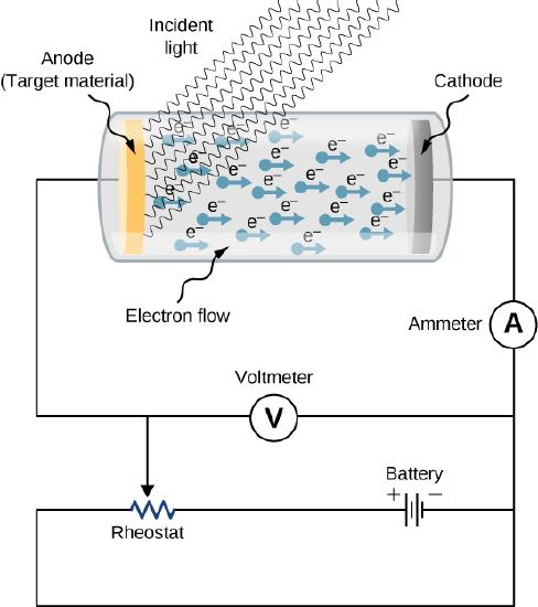
When the target material is not exposed to radiation, no current is registered in this circuit because the circuit is broken (note, there is a gap between the electrodes). But when the target material is connected to the negative terminal of a battery and exposed to radiation, a current is registered in this circuit; this current is called the photocurrent . Suppose that we now reverse the potential difference between the electrodes so that the target material now connects with the positive terminal of a battery, and then we slowly increase the voltage. The photocurrent gradually dies out and eventually stops flowing completely at some value of this reversed voltage. The potential difference at which the photocurrent stops flowing is called the stopping potential .
Characteristics of the Photoelectric Effect
The photoelectric effect has three important characteristics that cannot be explained by classical physics: (1) the absence of a lag time, (2) the independence of the kinetic energy of photoelectrons on the intensity of incident radiation, and (3) the presence of a cut-off frequency. Let’s examine each of these characteristics.
The absence of lag time
When radiation strikes the target material in the electrode, electrons are emitted almost instantaneously, even at very low intensities of incident radiation. This absence of lag time contradicts our understanding based on classical physics. Classical physics predicts that for low-energy radiation, it would take significant time before irradiated electrons could gain sufficient energy to leave the electrode surface; however, such an energy buildup is not observed.
The intensity of incident radiation and the kinetic energy of photoelectrons
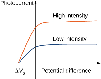
Typical experimental curves are shown in Figure \(\PageIndex{2}\), in which the photocurrent is plotted versus the applied potential difference between the electrodes. For the positive potential difference, the current steadily grows until it reaches a plateau. Furthering the potential increase beyond this point does not increase the photocurrent at all. A higher intensity of radiation produces a higher value of photocurrent. For the negative potential difference, as the absolute value of the potential difference increases, the value of the photocurrent decreases and becomes zero at the stopping potential. For any intensity of incident radiation, whether the intensity is high or low, the value of the stopping potential always stays at one value.
To understand why this result is unusual from the point of view of classical physics, we first have to analyze the energy of photoelectrons. A photoelectron that leaves the surface has kinetic energy \(K\). It gained this energy from the incident electromagnetic wave. In the space between the electrodes, a photoelectron moves in the electric potential and its energy changes by the amount \(q \Delta V\), where \(\Delta V\) is the potential difference and \(q = -e\). Because no forces are present but electric force, by applying the work-energy theorem, we obtain the energy balance \(\Delta K - e\Delta V = 0\) for the photoelectron, where \(\Delta K\) is the change in the photoelectron’s kinetic energy. When the stopping potential \(-\Delta V_s\) is applied, the photoelectron loses its initial kinetic energy \(K_i\) and comes to rest. Thus, its energy balance becomes \((0 - K_i) - e(-\Delta V_s) = 0\), so that \(K_i = e\Delta V_s\). In the presence of the stopping potential, the largest kinetic energy \(K_{max}\) that a photoelectron can have is its initial kinetic energy, which it has at the surface of the photoelectrode. Therefore, the largest kinetic energy of photoelectrons can be directly measured by measuring the stopping potential:
\[K_{max} = e\Delta V_s. \label{PEexpt} \]
At this point we can see where the classical theory is at odds with the experimental results. In classical theory, the photoelectron absorbs electromagnetic energy in a continuous way; this means that when the incident radiation has a high intensity, the kinetic energy in Equation \ref{PEexpt} is expected to be high. Similarly, when the radiation has a low intensity, the kinetic energy is expected to be low. But the experiment shows that the maximum kinetic energy of photoelectrons is independent of the light intensity.
The presence of a cut-off frequency
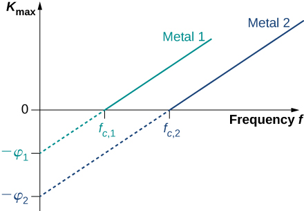
For any metal surface, there is a minimum frequency of incident radiation below which photocurrent does not occur. The value of this cut-off frequency for the photoelectric effect is a physical property of the metal: Different materials have different values of cut-off frequency. Experimental data show a typical linear trend (Figure \(\PageIndex{3}\)). The kinetic energy of photoelectrons at the surface grows linearly with the increasing frequency of incident radiation. Measurements for all metal surfaces give linear plots with one slope. None of these observed phenomena is in accord with the classical understanding of nature. According to the classical description, the kinetic energy of photoelectrons should not depend on the frequency of incident radiation at all, and there should be no cut-off frequency. Instead, in the classical picture, electrons receive energy from the incident electromagnetic wave in a continuous way, and the amount of energy they receive depends only on the intensity of the incident light and nothing else. So in the classical understanding, as long as the light is shining, the photoelectric effect is expected to continue.
The Work Function
The photoelectric effect was explained in 1905 by A. Einstein . Einstein reasoned that if Planck’s hypothesis about energy quanta was correct for describing the energy exchange between electromagnetic radiation and cavity walls, it should also work to describe energy absorption from electromagnetic radiation by the surface of a photoelectrode. He postulated that an electromagnetic wave carries its energy in discrete packets. Einstein’s postulate goes beyond Planck’s hypothesis because it states that the light itself consists of energy quanta. In other words, it states that electromagnetic waves are quantized.
In Einstein’s approach, a beam of monochromatic light of frequency \(f\) is made of photons. A photon is a particle of light. Each photon moves at the speed of light and carries an energy quantum \(E_f\). A photon’s energy depends only on its frequency \(f\). Explicitly, the energy of a photon is
\[E_f = hf \label{planck} \]
where \(h\) is Planck’s constant. In the photoelectric effect, photons arrive at the metal surface and each photon gives away all of its energy to only one electron on the metal surface. This transfer of energy from photon to electron is of the “all or nothing” type, and there are no fractional transfers in which a photon would lose only part of its energy and survive. The essence of a quantum phenomenon is either a photon transfers its entire energy and ceases to exist or there is no transfer at all. This is in contrast with the classical picture, where fractional energy transfers are permitted. Having this quantum understanding, the energy balance for an electron on the surface that receives the energy \(E_f\) from a photon is
\[E_f = K_{max} + \phi \nonumber \]
where \(K_max\) is the kinetic energy, given by Equation \ref{PEexpt}, that an electron has at the very instant it gets detached from the surface. In this energy balance equation, \(\phi\) is the energy needed to detach a photoelectron from the surface. This energy \(\phi\) is called the work function of the metal. Each metal has its characteristic work function, as illustrated in Table \(\PageIndex{1}\). To obtain the kinetic energy of photoelectrons at the surface, we simply invert the energy balance equation and use Equation \ref{planck} to express the energy of the absorbed photon. This gives us the expression for the kinetic energy of photoelectrons, which explicitly depends on the frequency of incident radiation:
\[K_{max}=hf−ϕ \label{PEeffect} \]
Equation \ref{PEeffect} has a simple mathematical form but its physics is profound. We can now elaborate on the physical meaning behind this equation.
In Einstein’s interpretation, interactions take place between individual electrons and individual photons. The absence of a lag time means that these one-on-one interactions occur instantaneously. This interaction time cannot be increased by lowering the light intensity. The light intensity corresponds to the number of photons arriving at the metal surface per unit time. Even at very low light intensities, the photoelectric effect still occurs because the interaction is between one electron and one photon. As long as there is at least one photon with enough energy to transfer it to a bound electron, a photoelectron will appear on the surface of the photoelectrode.
The existence of the cut-off frequency \(f_c\) for the photoelectric effect follows from Equation \ref{PEeffect} because the kinetic energy \(K_{max}\) of the photoelectron can take only positive values. This means that there must be some threshold frequency for which the kinetic energy is zero, \(0 = hf_c - \phi\). In this way, we obtain the explicit formula for cut-off frequency:
\[f_c = \frac{\phi}{h}. \label{6.15} \]
Cut-off frequency depends only on the work function of the metal and is in direct proportion to it. When the work function is large (when electrons are bound fast to the metal surface), the energy of the threshold photon must be large to produce a photoelectron, and then the corresponding threshold frequency is large. Photons with frequencies larger than the threshold frequency \(f_c\) always produce photoelectrons because they have \(K_{max} > 0\). Photons with frequencies smaller than \(f_c\) do not have enough energy to produce photoelectrons. Therefore, when incident radiation has a frequency below the cut-off frequency, the photoelectric effect is not observed. Because frequency \(f\) and wavelength \(\lambda\) of electromagnetic waves are related by the fundamental relation \(\lambda f = c\) (where cc is the speed of light in vacuum), the cut-off frequency has its corresponding cut-off wavelength \(\lambda_c\):
\[\lambda_c = \frac{c}{f_c} = \frac{c}{\phi /h} = \frac{hc}{\phi}. \label{6.16} \]
In this equation, \(hc = 1240 \, eV \cdot nm\). Our observations can be restated in the following equivalent way: When the incident radiation has wavelengths longer than the cut-off wavelength, the photoelectric effect does not occur.
\(\PageIndex{1}\): Photoelectric Effect for Silver
Radiation with wavelength 300 nm is incident on a silver surface. Will photoelectrons be observed?
Photoelectrons can be ejected from the metal surface only when the incident radiation has a shorter wavelength than the cut-off wavelength. The work function of silver is \(\phi = 4.73 \, eV\) (Table \(\PageIndex{1}\)). To make the estimate, we use Equation \ref{6.16}.
The threshold wavelength for observing the photoelectric effect in silver is
\[\begin{align*} \lambda_c &= \frac{hc}{\phi} \\[4pt] &= \frac{1240 \, eV \cdot nm}{4.73 \, eV} = 262 \, nm. \end{align*} \nonumber \]
The incident radiation has wavelength 300 nm, which is longer than the cut-off wavelength; therefore, photoelectrons are not observed.
Significance
If the photoelectrode were made of sodium instead of silver, the cut-off wavelength would be 504 nm and photoelectrons would be observed.
Equation \ref{PEeffect} in Einstein’s model tells us that the maximum kinetic energy of photoelectrons is a linear function of the frequency of incident radiation, which is illustrated in Figure \(\PageIndex{3}\). For any metal, the slope of this plot has a value of Planck’s constant. The intercept with the \(K_{max}\)-axis gives us a value of the work function that is characteristic for the metal. On the other hand, \(K_{max}\) can be directly measured in the experiment by measuring the value of the stopping potential \(\delta V_s\) (see Equation \ref{PEexpt}) at which the photocurrent stops. These direct measurements allow us to determine experimentally the value of Planck’s constant, as well as work functions of materials.
Einstein’s model also gives a straightforward explanation for the photocurrent values shown in Figure \(\PageIndex{3}\). For example, doubling the intensity of radiation translates to doubling the number of photons that strike the surface per unit time. The larger the number of photons, the larger is the number of photoelectrons, which leads to a larger photocurrent in the circuit. This is how radiation intensity affects the photocurrent. The photocurrent must reach a plateau at some value of potential difference because, in unit time, the number of photoelectrons is equal to the number of incident photons and the number of incident photons does not depend on the applied potential difference at all, but only on the intensity of incident radiation. The stopping potential does not change with the radiation intensity because the kinetic energy of photoelectrons (see Equation \ref{PEeffect}) does not depend on the radiation intensity.
Example \(\PageIndex{2}\): Work Function and Cut-Off Frequency
When a 180-nm light is used in an experiment with an unknown metal, the measured photocurrent drops to zero at potential – 0.80 V. Determine the work function of the metal and its cut-off frequency for the photoelectric effect.
To find the cut-off frequency \(f_c\), we use Equation \ref{6.15}, but first we must find the work function \(\phi\). To find \(\phi\), we use Equation \ref{PEexpt} and Equation \ref{PEeffect}. Photocurrent drops to zero at the stopping value of potential, so we identify \(\Delta V_s = 0.8 V\).
We use Equation \ref{PEexpt} to find the kinetic energy of the photoelectrons:
\[K_{max} = e\Delta V_s = e(0.80 V) = 0.80 \, eV. \nonumber \]
Now we solve Equation for \(\phi\):
\[\phi = hf - K_{max} = \frac{hc}{\lambda} - K_{max} = \frac{1240 \, eV \cdot m}{180 \, nm} − 0.80 \, eV = 6.09eV. \nonumber \]
Finally, we use Equation to find the cut-off frequency:
\[f_c = \frac{\phi}{h} \frac{6.09 \, eV}{4.136 \times 10^{-15} eV \cdot s} = 1.47 \times 10^{-15} Hz. \nonumber \]
In calculations like the one shown in this example, it is convenient to use Planck’s constant in the units of \(eV \cdot s\) and express all energies in eV instead of joules.
Example \(\PageIndex{3}\): The Photon Energy and Kinetic Energy of Photoelectrons
A 430-nm violet light is incident on a calcium photoelectrode with a work function of 2.71 eV. Find the energy of the incident photons and the maximum kinetic energy of ejected electrons.
The energy of the incident photon is \(E_f = hf = hc/\lambda\),, where we use \(f\lambda = c\). To obtain the maximum energy of the ejected electrons, we use Equation \ref{6.16}.
\[E_f = \frac{hc}{\lambda} = \frac{1240 \, eV \cdot nm}{430 \, nm} = 2.88 \, eV, \, K_{max} = E_f − \phi = 2.88 \, eV − 2.71 \, eV = 0.17 \, eV \nonumber \]
In this experimental setup, photoelectrons stop flowing at the stopping potential of 0.17 V.
Exercise \(\PageIndex{1}\)
A yellow 589-nm light is incident on a surface whose work function is 1.20 eV. What is the stopping potential? What is the cut-off wavelength?
\(-0.91 \, V\) 1040 nm
Exercise \(\PageIndex{2}\)
Cut-off frequency for the photoelectric effect in some materials is \(8.0×10^{13}Hz.\) When the incident light has a frequency of \(1.2×10^{14}Hz\), the stopping potential is measured as – 0.16 V. Estimate a value of Planck’s constant from these data (in units J⋅sJ·s and eV⋅seV·s) and determine the percentage error of your estimation.
\(h = 6.40 \times 10^{-34} J \cdot s = 4.0 \times 10^{-15} eV \cdot s\); \(-3.5\%\)
Talk to our experts
1800-120-456-456
Photoelectric Effect and Stopping Potential with Work Function and Derivation for JEE
- Photoelectric Effect And Stopping Potential

What is the Photoelectric Effect?
In 1905, Albert Einstein gave his Nobel prize-winning paper on the discrete quantisation of energy in electromagnetic radiation. The core premise of this work was based on the data obtained from the photoelectric effect experiments done by Aleksandr Stoletov. To explain the photoelectric effect, they found a correlation between the intensity of light and the number of electrons emitted. According to the photoelectric effect, when an electromagnetic wave of a specific frequency (energy) is bombarded on a metal, the electrons inside the metal are ejected and become known as photoelectrons through a process known as photoemission.
Work Function
The work function draws a barrier between emission and absorption. If the incident electromagnetic wave does not have energy equal to the work function of the material, electrons will not be ejected from the atoms of the metal. Quantised wave packets can activate emission if they have energies greater than the work function of the metal.
In solid-state physics, the work function is the minimum thermodynamic work needed to remove an electron from a solid to a point in the vacuum immediately outside the solid surface. Work function is a property of a material, which is defined as the minimum quantity of energy required to remove an electron to infinity from the surface of a given solid.
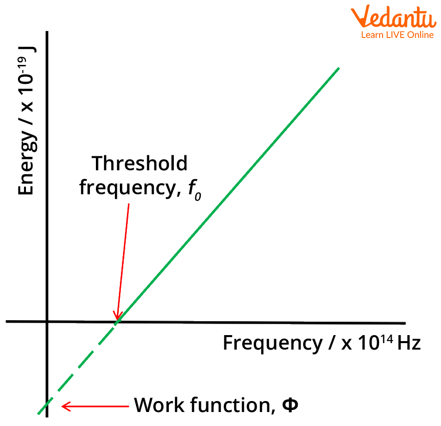
Energy versus frequency graph
What is Stopping Potential?
Stopping potential, or cut-off potential, is defined as the required potential for stopping the removal of an electron from a metal surface when the incident light energy is greater than the work potential of the metal on which the incident light is focused. The work function and stopping potential tend to mean the same thing in terms of the photoelectric effect.
Derivation of Maximum Kinetic Energy:
The concept of the derivation of Maximum Kinetic Energy using Einstein's explanation of the photoelectric effect in simpler terms:
Einstein figured out that light energy comes in small packets called photons. Each photon has a certain amount of energy, and when it hits a metal surface, an electron can absorb that energy. If the absorbed energy is enough to overcome the "stickiness" of the metal (called work function), the electron gains extra energy and gets kicked out from the metal.
Energy of the photon (hf) ≥ Work function (Φ) + Maximum Kinetic Energy (KEmax)
By rearranging the formula, we find the maximum kinetic energy:
KEmax = hf - Φ
Two important things to note:
Threshold Frequency: If the frequency of light is below a certain value (ν₀ = Φ/h), the absorbed energy is not enough to free the electron, so nothing happens.
Frequency Dependence: If the light frequency is above the threshold, the more the frequency increases, the more extra energy the electron gets. This is different from what classical physics would predict, where brighter light should just give more energy. In the photoelectric effect, it's the frequency that matters, not the brightness.
Derivation of Photoelectric Effect and Stopping Potential Formula
To derive Einstein’s photoelectric equation formula for stopping potential, we need to identify the required variables and parameters first. As we know
$ c=\nu \lambda$
where c is the speed of light, 𝛎 is the frequency of the electromagnetic wave, and $\lambda$ is the measure of the wavelength of the electromagnetic wave.
$\nu=\dfrac{c}{\lambda}$
$\Rightarrow E=h \nu$……..(1)
Here, E is the energy of the electromagnetic wave.
Therefore, we can use the known parameters to calculate the kinetic energy of the photoelectrons.
$K E_{\max }=\dfrac{h c}{\lambda}-\phi $……..(2)
The stopping potential $\phi$ can be given as
$\phi=\dfrac{h c}{\lambda}-K E_{\max }$
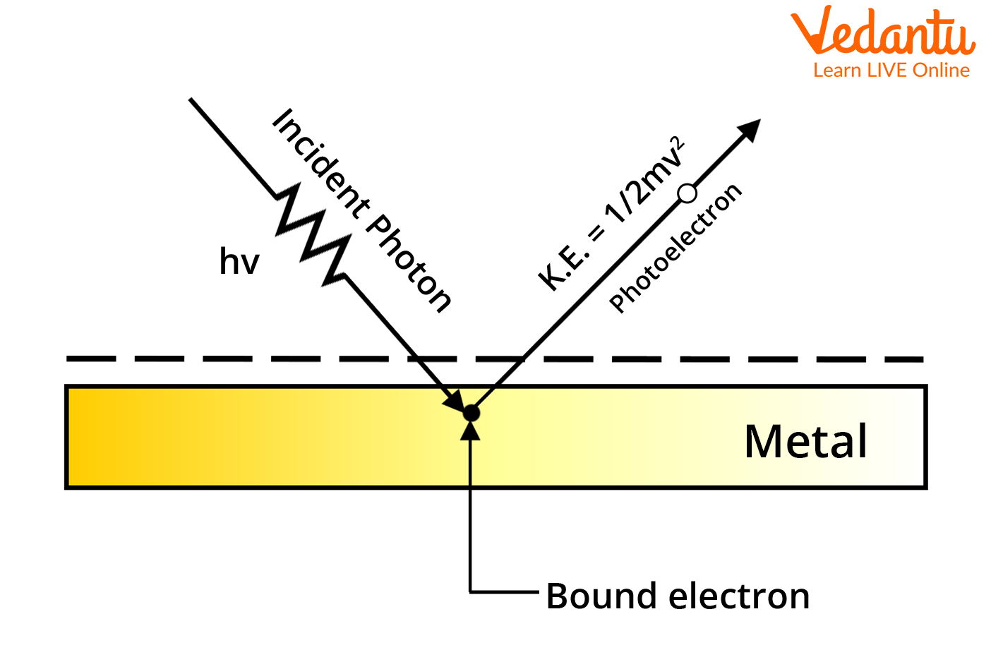
Process of Photoemission
Now the kinetic energy can be written as
$K E_{\max }=\dfrac{1}{2} m v_{\max}^{2} $
Also, the energy of a photo equal to the work function can be written as
$\begin{align} &\phi=\dfrac{h c}{\lambda_{0}} \\ &\phi=h \nu_{0} \end{align}$
So, the equation for the stopping potential can be written as
$\begin{align} &h \nu_{0}=\dfrac{h c}{\lambda}-\dfrac{1}{2} m v_{\max }^{2} \\ &h \nu_{0}=h \nu-\dfrac{1}{2} m v_{\max }^{2} \end{align}$
We can also write
$\begin{align} &\dfrac{1}{2} m v_{\max }^{2}=h \nu-h v_{0} \\ &\dfrac{1}{2} m v_{\max }^{2}=h\left(\nu-\nu_{0}\right) \end{align}$
The photoelectric effect can be derived from the concept of Planck's quantum theory. Photons travel in discrete energy packets, where the energy of one photon is given by the equation (1). $\nu$ is the frequency of the incident photon. ‘h’ is the Planck’s constant whose value is $h=6.6260715 \times 10^{-34} \mathrm{~J} . \mathrm{s}$ the units are Joule-Second.
To summarise the variables used in the derivation of the photoelectric equation, we have
h, which is the Planck constant.
$\nu$ , which is the frequency of the radiation in question.
$\lambda$, which is the wavelength of the radiation.
c, which is the speed of light in a vacuum.
E, which is the energy of the photon.
There is a single interaction that sums up the photoelectric effect, the incidence of a photon on the metal surface, and its interaction with the electron bound to the surface of the metal within the interatomic interactions.
Derivation of Key Equations Governing the Photoelectric Effect
Let's delve into the derivation of the key equations governing the photoelectric effect. Starting with the conservation of energy, we equate the energy of the incident photon to the sum of the work function and the kinetic energy of the ejected electron:
hf=Φ+1/2 mv 2
Simplifying and using the de Broglie wavelength (λ= h/mv), we arrive at the expression for kinetic energy:
This derivation provides a deeper insight into the relationship between incident light, work function, and the resulting kinetic energy of ejected electrons.
Dependence of Photoelectric Effect on Different Parameters
For a light of any given frequency, the photoelectric current is directly proportional to the intensity of light.
If the frequency of light is no greater than the threshold frequency, the emission of photoelectrons will be stopped, no matter how intense the light rays are.
The maximum kinetic energy of the photoelectrons emitted is independent of the intensity of light. As the frequency of light increases over the threshold frequency, the kinetic energy of the electrons also increases.
The process of photoemission is instantaneous, as it depends on the quanta of energy the radiation brings with it.
Applications of the Photoelectric Effect:
Solar Panels: They use special metals to turn light into electricity from various wavelengths.
Motion and Position Sensors: These sensors use a material that reacts to light (UV or IR) along with LEDs. When something blocks the light, a change in electricity is noted.
Lighting Sensors (e.g., in smartphones): Adjust screen brightness automatically based on the light intensity, thanks to the photoelectric effect generating current.
Digital Cameras: Detect and capture light by using sensors that respond to different colors.
X-Ray Photoelectron Spectroscopy (XPS): Uses X-rays to learn about surfaces, like elemental and chemical composition.
Burglar Alarms: Photoelectric cells help in detecting intruders.
Photomultipliers: Used to find very low levels of light.
Video Camera Tubes (early TV): Photoelectric effect was key in early television cameras.
Night Vision Devices: They work because of the photoelectric effect.
Chemical Analysis: Photoelectric effect aids in studying nuclear processes and analyzing materials by examining the energy of emitted electrons.
The phenomenon of the photoelectric effect was discovered by the works of Heinrich Hertz, Albert Einstein, Max Planck, and others during the late 19th to early 20th century. The photoelectric effect can be defined as a phenomenon during which electrons are emitted from the surface of the metal when the light of a suitable wavelength is incident on it. These electrons are termed photoelectrons.
This emission occurs due to the electrons absorbing energy from the electromagnetic radiation and using this agitation to break free from the intra-atomic forces of attraction in the metal. This spontaneous emission of electrons is called photoemission. The current generated due to this emission is referred to as photocurrent. This phenomenon converts light energy into electrical energy.
FAQs on Photoelectric Effect and Stopping Potential with Work Function and Derivation for JEE
1. How many questions are asked about the photoelectric effect in JEE?
Around 1-2 questions would be asked on this topic for the exam which makes around 4-8 marks in the total of the exam. Preparing this concept will help you gain these easy marks in the total. Preparing previous years’ questions will help you to understand how the questions are framed on related concepts and will give you an idea of how to tackle such problems with ease. Try to search for unusual problems to get insight into the relevance of the photoelectric effect in JEE .
2. What is the physical significance of the photoelectric effect?
The photoelectric effect proves the behaviour of light as a particle-type nature. This is in direct contrast with the theory of the wave nature of light, which is shown in experiments related to interference, diffraction, etc. For studying both the natures of light as a wave and as a particle, this phenomenon of the photoelectric effect is very crucial. It’s true that the energy of the radiation is uniformly distributed along the wavefront of the electromagnetic wave, however, Planck and Einstein proved that the light energy is quantised in the form of wave packets known as quanta.
3. What is the photoelectric effect?
The photoelectric effect is the phenomenon where electrons are ejected from a material's surface when light shines on it, provided the light has enough energy. This ejected electron is called a photoelectron.
4. What is work function?
The work function (Φ) of a material is the minimum energy required to eject an electron from its bound state in the material to the vacuum level. It is usually expressed in electron volts (eV).
5. What is stopping potential?
The stopping potential (V₀) is the minimum potential difference that needs to be applied to stop the most energetic photoelectrons emitted from a material. It is directly proportional to the maximum kinetic energy of the photoelectrons.
6. Relationship between work function and stopping potential:
Einstein's photoelectric equation relates the work function of a material to the stopping potential and the frequency (ν) of the incident light:
hf = Φ + ½ mv₀²
where h is Planck's constant, e is the electron's charge, and m is the electron's mass.
7. Derivation of Einstein's photoelectric equation:
Consider an electron bound in a material with an energy level E below the vacuum level.
When light with frequency ν hits the material, a photon with energy hf can be absorbed by the electron.
If the absorbed energy is greater than or equal to the work function (hf ≥ Φ), the electron can be ejected from the material with kinetic energy KE:
KE = hf - Φ
The stopping potential is applied to oppose the motion of the photoelectrons. At the stopping potential, the kinetic energy of the most energetic photoelectrons is converted into electrical potential energy:
eVo = ½ mv₀²
Combining equations 3 and 4, we get Einstein's photoelectric equation.
8. What is the significance of the photoelectric effect?
The photoelectric effect provided experimental evidence for the quantization of light, supporting the idea of photons.
It has numerous applications, including solar cells, photomultiplier tubes, and electron microscopes.

- IIT JEE Study Material
Photoelectric Effect
The photoelectric effect is a phenomenon in which electrons are ejected from the surface of a metal when light is incident on it. These ejected electrons are called photoelectrons . It is important to note that the emission of photoelectrons and the kinetic energy of the ejected photoelectrons is dependent on the frequency of the light that is incident on the metal’s surface. The process through which photoelectrons are ejected from the surface of the metal due to the action of light is commonly referred to as photoemission .
Download Complete Chapter Notes of Structure of Atom Download Now
The photoelectric effect occurs because the electrons at the surface of the metal tend to absorb energy from the incident light and use it to overcome the attractive forces that bind them to the metallic nuclei. An illustration detailing the emission of photoelectrons as a result of the photoelectric effect is provided below.

History of the Photoelectric Effect Principle Formula Laws Governing the Photoelectric Effect Experimental Study of the Photoelectric Effect Einstien’s Photoelectric Equation Graphs Applications Solved Problems (Numericals)
Recommended Video
Photoelectric effect – basics.

Hertz and Lenard’s Observation

History of the Photoelectric Effect
The photoelectric effect was first introduced by Wilhelm Ludwig Franz Hallwachs in the year 1887, and the experimental verification was done by Heinrich Rudolf Hertz. They observed that when a surface is exposed to electromagnetic radiation at a higher threshold frequency, the radiation is absorbed, and the electrons are emitted. Today, we study the photoelectric effect as a phenomenon that involves a material absorbing electromagnetic radiation and releasing electrically charged particles.
To be more precise, light incident on the surface of a metal in the photoelectric effect causes electrons to be ejected. The electron ejected due to the photoelectric effect is called a photoelectron and is denoted by e – . The current produced as a result of the ejected electrons is called photoelectric current.

Explaining the Photoelectric Effect: The Concept of Photons
The photoelectric effect cannot be explained by considering light as a wave. However, this phenomenon can be explained by the particle nature of light, in which light can be visualised as a stream of particles of electromagnetic energy. These ‘particles’ of light are called photons . The energy held by a photon is related to the frequency of the light via Planck’s equation .
E = h𝜈 = hc/λ
- E denotes the energy of the photon
- h is Planck’s constant
- 𝜈 denotes the frequency of the light
- c is the speed of light (in a vacuum)
- λ is the wavelength of the light
Thus, it can be understood that different frequencies of light carry photons of varying energies. For example, the frequency of blue light is greater than that of red light (the wavelength of blue light is much shorter than the wavelength of red light). Therefore, the energy held by a photon of blue light will be greater than the energy held by a photon of red light.
Threshold Energy for the Photoelectric Effect
For the photoelectric effect to occur, the photons that are incident on the surface of the metal must carry sufficient energy to overcome the attractive forces that bind the electrons to the nuclei of the metals. The minimum amount of energy required to remove an electron from the metal is called the threshold energy (denoted by the symbol Φ). For a photon to possess energy equal to the threshold energy, its frequency must be equal to the threshold frequency (which is the minimum frequency of light required for the photoelectric effect to occur). The threshold frequency is usually denoted by the symbol 𝜈 th , and the associated wavelength (called the threshold wavelength) is denoted by the symbol λ th . The relationship between the threshold energy and the threshold frequency can be expressed as follows.
Φ = h𝜈 th = hc/λ th
Relationship between the Frequency of the Incident Photon and the Kinetic Energy of the Emitted Photoelectron
Therefore, the relationship between the energy of the photon and the kinetic energy of the emitted photoelectron can be written as follows:
E photon = Φ + E electron
⇒ h𝜈 = h𝜈 th + ½m e v 2
- E photon denotes the energy of the incident photon, which is equal to h𝜈
- Φ denotes the threshold energy of the metal surface, which is equal to h𝜈 th
- E electron denotes the kinetic energy of the photoelectron, which is equal to ½m e v 2 (m e = Mass of electron = 9.1*10 -31 kg)
If the energy of the photon is less than the threshold energy, there will be no emission of photoelectrons (since the attractive forces between the nuclei and the electrons cannot be overcome). Thus, the photoelectric effect will not occur if 𝜈 < 𝜈 th . If the frequency of the photon is exactly equal to the threshold frequency (𝜈 = 𝜈 th ), there will be an emission of photoelectrons, but their kinetic energy will be equal to zero. An illustration detailing the effect of the frequency of the incident light on the kinetic energy of the photoelectron is provided below.

From the image, it can be observed that
- The photoelectric effect does not occur when the red light strikes the metallic surface because the frequency of red light is lower than the threshold frequency of the metal.
- The photoelectric effect occurs when green light strikes the metallic surface, and photoelectrons are emitted.
- The photoelectric effect also occurs when blue light strikes the metallic surface. However, the kinetic energies of the emitted photoelectrons are much higher for blue light than for green light. This is because blue light has a greater frequency than green light.
It is important to note that the threshold energy varies from metal to metal. This is because the attractive forces that bind the electrons to the metal are different for different metals. It can also be noted that the photoelectric effect can also take place in non-metals, but the threshold frequencies of non-metallic substances are usually very high.
Einstein’s Contributions towards the Photoelectric Effect
The photoelectric effect is the process that involves the ejection or release of electrons from the surface of materials (generally a metal) when light falls on them. The photoelectric effect is an important concept that enables us to clearly understand the quantum nature of light and electrons.
After continuous research in this field, the explanation for the photoelectric effect was successfully explained by Albert Einstein. He concluded that this effect occurred as a result of light energy being carried in discrete quantised packets. For this excellent work, he was honoured with the Nobel Prize in 1921.
According to Einstein, each photon of energy E is
Where E = Energy of the photon in joule
h = Plank’s constant (6.626 × 10 -34 J.s)
ν = Frequency of photon in Hz
Properties of the Photon
- For a photon, all the quantum numbers are zero.
- A photon does not have any mass or charge, and they are not reflected in a magnetic and electric field.
- The photon moves at the speed of light in empty space.
- During the interaction of matter with radiation, radiation behaves as it is made up of small particles called photons.
- Photons are virtual particles. The photon energy is directly proportional to its frequency and inversely proportional to its wavelength.
- The momentum and energy of the photons are related, as given below
E = p.c where
p = Magnitude of the momentum
c = Speed of light
Definition of the Photoelectric Effect
Principle of the photoelectric effect.
The law of conservation of energy forms the basis for the photoelectric effect.
Minimum Condition for Photoelectric Effect
Threshold frequency (γ th ).
It is the minimum frequency of the incident light or radiation that will produce a photoelectric effect, i.e., the ejection of photoelectrons from a metal surface is known as the threshold frequency for the metal. It is constant for a specific metal but may be different for different metals.
If γ = Frequency of the incident photon and γ th = Threshold frequency, then,
- If γ < γ Th , there will be no ejection of photoelectron and, therefore, no photoelectric effect.
- If γ = γ Th , photoelectrons are just ejected from the metal surface; in this case, the kinetic energy of the electron is zero.
- If γ > γ Th , then photoelectrons will come out of the surface, along with kinetic energy.
Threshold Wavelength (λ th )
During the emission of electrons, a metal surface corresponding to the greatest wavelength to incident light is known as threshold wavelength.
λ th = c/γ th
For wavelengths above this threshold, there will be no photoelectron emission. For λ = wavelength of the incident photon, then
- If λ < λ Th , then the photoelectric effect will take place, and ejected electron will possess kinetic energy.
- If λ = λ Th, then just the photoelectric effect will take place, and the kinetic energy of ejected photoelectron will be zero.
- If λ > λ Th, there will be no photoelectric effect.
Work Function or Threshold Energy (Φ)
The minimal energy of thermodynamic work that is needed to remove an electron from a conductor to a point in the vacuum immediately outside the surface of the conductor is known as work function/threshold energy.
Φ = hγ th = hc/λ th
The work function is the characteristic of a given metal. If E = energy of an incident photon, then
- If E < Φ, no photoelectric effect will take place.
- If E = Φ, just a photoelectric effect will take place, but the kinetic energy of ejected photoelectron will be zero
- If E > photoelectron will be zero
- If E > Φ, the photoelectric effect will take place along with the possession of the kinetic energy by the ejected electron.
Photoelectric Effect Formula
According to Einstein’s explanation of the photoelectric effect ,
The energy of photon = Energy needed to remove an electron + Kinetic energy of the emitted electron
i.e., hν = W + E
- ν is the frequency of the incident photon
- W is a work function
- E is the maximum kinetic energy of ejected electrons: 1/2 mv²
Laws Governing the Photoelectric Effect
- For a light of any given frequency,; (γ > γ Th ), the photoelectric current is directly proportional to the intensity of light.
- For any given material, there is a certain minimum (energy) frequency, called threshold frequency, below which the emission of photoelectrons stops completely, no matter how high the intensity of incident light is.
- The maximum kinetic energy of the photoelectrons is found to increase with the increase in the frequency of incident light, provided the frequency (γ > γ Th ) exceeds the threshold limit. The maximum kinetic energy is independent of the intensity of light.
- The photo-emission is an instantaneous process.
Experimental Study of the Photoelectric Effect
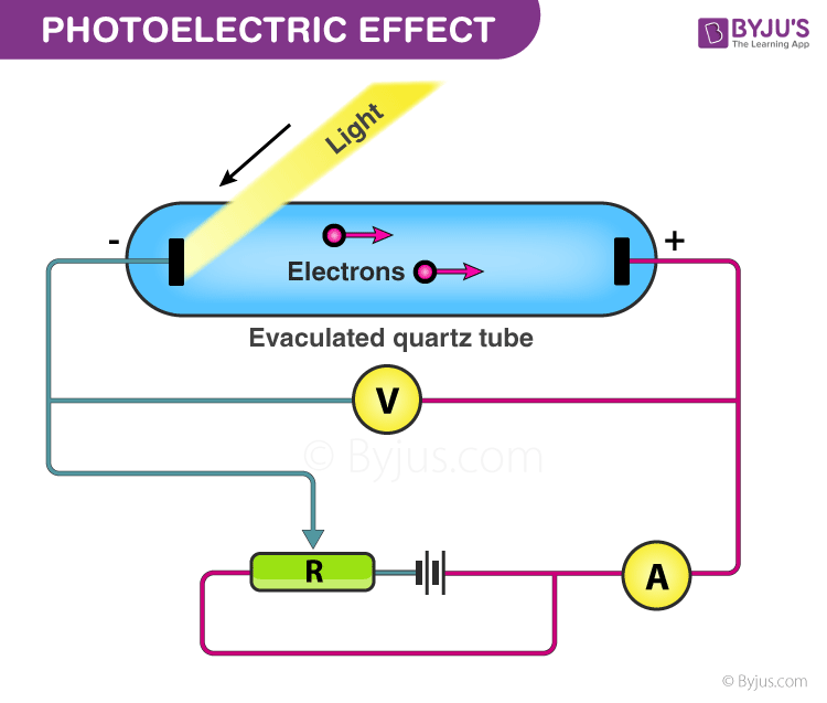
Photoelectric Effect: Experimental Setup
The given experiment is used to study the photoelectric effect experimentally. In an evacuated glass tube, two zinc plates, C and D, are enclosed. Plates C acts as an anode, and D acts as a photosensitive plate.
Two plates are connected to battery B and ammeter A. If the radiation is incident on plate D through a quartz window, W electrons are ejected out of the plate, and current flows in the circuit. This is known as photocurrent. Plate C can be maintained at desired potential (+ve or – ve) with respect to plate D.
Characteristics of the Photoelectric Effect
- The threshold frequency varies with the material, it is different for different materials.
- The photoelectric current is directly proportional to the light intensity.
- The kinetic energy of the photoelectrons is directly proportional to the light frequency.
- The stopping potential is directly proportional to the frequency, and the process is instantaneous.
Factors Affecting the Photoelectric Effect
With the help of this apparatus, we will now study the dependence of the photoelectric effect on the following factors:
- The intensity of incident radiation.
- A potential difference between the metal plate and collector.
- Frequency of incident radiation.
Effects of Intensity of Incident Radiation on Photoelectric Effect
The potential difference between the metal plate, collector and frequency of incident light is kept constant, and the intensity of light is varied.
The electrode C, i.e., the collecting electrode, is made positive with respect to D (metal plate). For a fixed value of frequency and the potential between the metal plate and collector, the photoelectric current is noted in accordance with the intensity of incident radiation.
It shows that photoelectric current and intensity of incident radiation both are proportional to each other. The photoelectric current gives an account of the number of photoelectrons ejected per sec.
Effects of Potential Difference between the Metal Plate and the Collector on the Photoelectric Effect
The frequency of incident light and intensity is kept constant, and the potential difference between the plates is varied.
Keeping the intensity and frequency of light constant, the positive potential of C is increased gradually. Photoelectric current increases when there is a positive increase in the potential between the metal plate and the collector up to a characteristic value.
There is no change in photoelectric current when the potential is increased higher than the characteristic value for any increase in the accelerating voltage. This maximum value of the current is called saturation current.
Effect of Frequency on Photoelectric Effect
The intensity of light is kept constant, and the frequency of light is varied.
For a fixed intensity of incident light, variation in the frequency of incident light produces a linear variation of the cut-off potential/stopping potential of the metal. It is shown that the cut-off potential (Vc) is linearly proportional to the frequency of incident light.
The kinetic energy of the photoelectrons increases directly proportionally to the frequency of incident light to completely stop the photoelectrons. We should reverse and increase the potential between the metal plate and collector in (negative value) so the emitted photoelectron can’t reach the collector.
Einstein’s Photoelectric Equation
According to Einstein’s theory of the photoelectric effect, when a photon collides inelastically with electrons, the photon is absorbed completely or partially by the electrons. So if an electron in a metal absorbs a photon of energy, it uses the energy in the following ways.
Some energy Φ 0 is used in making the surface electron free from the metal. It is known as the work function of the material. Rest energy will appear as kinetic energy (K) of the emitted photoelectrons.
Einstein’s Photoelectric Equation Explains the Following Concepts
- The frequency of the incident light is directly proportional to the kinetic energy of the electrons, and the wavelengths of incident light are inversely proportional to the kinetic energy of the electrons.
- If γ = γ th or λ =λ th then v max = 0
- γ < γ th or λ > λ th : There will be no emission of photoelectrons.
- The intensity of the radiation or incident light refers to the number of photons in the light beam. More intensity means more photons and vice-versa. Intensity has nothing to do with the energy of the photon. Therefore, the intensity of the radiation is increased, and the rate of emission increases, but there will be no change in the kinetic energy of electrons. With an increasing number of emitted electrons, the value of the photoelectric current increases.
Different Graphs of the Photoelectric Equation
- Photoelectric current vs Retarding potential for different voltages
- Photoelectric current vs Retarding potential for different intensities
- Electron current vs Light Intensity
- Stopping potential vs Frequency
- Electron current vs Light frequency
- Electron kinetic energy vs Light frequency

Applications of the Photoelectric Effect
- Used to generate electricity in solar panels. These panels contain metal combinations that allow electricity generation from a wide range of wavelengths.
- Motion and Position Sensors: In this case, a photoelectric material is placed in front of a UV or IR LED. When an object is placed in between the Light-emitting diode (LED) and sensor, light is cut off, and the electronic circuit registers a change in potential difference
- Lighting sensors, such as the ones used in smartphones, enable automatic adjustment of screen brightness according to the lighting. This is because the amount of current generated via the photoelectric effect is dependent on the intensity of light hitting the sensor.
- Digital cameras can detect and record light because they have photoelectric sensors that respond to different colours of light.
- X-Ray Photoelectron Spectroscopy (XPS): This technique uses X-rays to irradiate a surface and measure the kinetic energies of the emitted electrons. Important aspects of the chemistry of a surface can be obtained, such as elemental composition, chemical composition, the empirical formula of compounds and chemical state.
- Photoelectric cells are used in burglar alarms.
- Used in photomultipliers to detect low levels of light.
- Used in video camera tubes in the early days of television.
- Night vision devices are based on this effect.
- The photoelectric effect also contributes to the study of certain nuclear processes. It takes part in the chemical analysis of materials since emitted electrons tend to carry specific energy that is characteristic of the atomic source.
Photoelectric Effect – JEE Advanced Concepts and Problems
Problems on the Photoelectric Effect
1. In a photoelectric effect experiment, the threshold wavelength of incident light is 260 nm and E (in eV) = 1237/λ (nm). Find the maximum kinetic energy of emitted electrons.
⇒ K max = (1237) × [(380 – 260)/380×260] = 1.5 eV
Therefore, the maximum kinetic energy of emitted electrons in the photoelectric effect is 1.5 eV.
2. In a photoelectric experiment, the wavelength of the light incident on metal is changed from 300 nm to 400 nm and (hc/e = 1240 nm-V). Find the decrease in the stopping potential.
hc/λ 1 = ϕ + eV 1 . . . . (i)
hc/λ 2 = ϕ + eV 2 . . . . (ii)
Equation (i) – (ii)
hc(1/λ 1 – 1/λ 2 ) = e × (V 1 – V 2 )
= (1240 nm V) × 100nm/(300nm × 400nm)
=12.4/12 ≈ 1V
Therefore, the decrease in the stopping potential during the photoelectric experiment is 1V.
3. When ultraviolet light with a wavelength of 230 nm shines on a particular metal plate, electrons are emitted from plate 1, crossing the gap to plate 2 and causing a current to flow through the wire connecting the two plates. The battery voltage is gradually increased until the current in the ammeter drops to zero, at which point the battery voltage is 1.30 V.

a) What is the energy of the photons in the beam of light in eV?
b) What is the maximum kinetic energy of the emitted electrons in eV?
Assuming that the wavelength corresponds to the wavelength in the vacuum.
f = 1.25 × 10 15 Hz
The energy of photon E = hf
E = (4.136 × 10 -15 )( 1.25 × 10 15)
Note: Planck’s constant in eV s = 4.136 × 10 -15 eV s
E = 5.17 eV.
b) The maximum kinetic energy related to the emitted electron is stopping potential. In this case, the stopping potential is 1.30V. So the maximum kinetic energy of the electrons is 1.30V.
Also Check out: JEE Main Photoelectric Effect Previous Year Questions with Solutions
Important Points to Remember
- If we consider the light with any given frequency, the photoelectric current is generally directly proportional to the intensity of light. However, the frequency should be above the threshold frequency in such a case.
- Below threshold frequency, the emission of photoelectrons completely stops despite the high intensity of incident light.
- A photoelectron’s maximum kinetic energy increases with an increase in the frequency of incident light. In this case, the frequency should exceed the threshold limit. Maximum kinetic energy is not affected by the intensity of light.
- Stopping potential is the negative potential of the opposite electrode when the photo-electric current falls to zero.
- The threshold frequency is described as the frequency when the photoelectric current stops below a particular frequency of incident light.
- The photoelectric effect establishes the quantum nature of radiation. This has been taken into account to be proof in favour of the particle nature of light.

Put your understanding of this concept to test by answering a few MCQs. Click ‘Start Quiz’ to begin!
Select the correct answer and click on the “Finish” button Check your score and answers at the end of the quiz
Visit BYJU’S for all JEE related queries and study materials
Your result is as below
Request OTP on Voice Call
Leave a Comment Cancel reply
Your Mobile number and Email id will not be published. Required fields are marked *
Post My Comment
Register with Aakash BYJU'S & Download Free PDFs
Register with byju's & watch live videos.
- Lecture Demonstration Manual
- Lab Manuals
- Instructional Videos
- PhotoSpheres
You are here
Table of contents.
- Experiment 1 - Magnetic Fields of Coils and Faraday's Law
- Experiment 2 - Microwave Optics
- Experiment 3 - Geometrical Optics
- Experiment 4 - Physical Optics
- Experiment 5 - Fluids and Thermodynamics
Experiment 6 - The Photoelectric Effect
- Experiment 7 - Radioactivity
- Photodiode with amplifier
- Batteries to operate amplifier and provide reverse voltage
- Digital voltmeter to read reverse voltage
- Source of monochromatic light beams to irradiate photocathode
- Neutral filter to vary light intensity
INTRODUCTION
The energy quantization of electromagnetic radiation in general, and of light in particular, is expressed in the famous relation
\begin{eqnarray} E &=& hf, \label{eqn_1} \end{eqnarray}
where \(E\) is the energy of the radiation, \(f\) is its frequency, and \(h\) is Planck's constant (6.63×10 -34 Js). The notion of light quantization was first introduced by Planck. Its validity is based on solid experimental evidence, most notably the photoelectric effect . The basic physical process underlying this effect is the emission of electrons in metals exposed to light. There are four aspects of photoelectron emission which conflict with the classical view that the instantaneous intensity of electromagnetic radiation is given by the Poynting vector \(\textbf{S}\):
\begin{eqnarray} \textbf{S} &=& (\textbf{E}\times\textbf{B})/\mu_0, \label{eqn_2} \end{eqnarray}
with \(\textbf{E}\) and \(\textbf{B}\) the electric and magnetic fields of the radiation, respectively, and μ 0 (4π×10 -7 Tm/A) the permeability of free space. Specifically:
No photoelectrons are emitted from the metal when the incident light is below a minimum frequency, regardless of its intensity. (The value of the minimum frequency is unique to each metal.)
Photoelectrons are emitted from the metal when the incident light is above a threshold frequency. The kinetic energy of the emitted photoelectrons increases with the frequency of the light.
The number of emitted photoelectrons increases with the intensity of the incident light. However, the kinetic energy of these electrons is independent of the light intensity.
Photoemission is effectively instantaneous.
Consider the conduction electrons in a metal to be bound in a well-defined potential. The energy required to release an electron is called the work function \(W_0\) of the metal. In the classical model, a photoelectron could be released if the incident light had sufficient intensity. However, Eq. \eqref{eqn_1} requires that the light exceed a threshold frequency \(f_{\textrm{t}}\) for an electron to be emitted. If \(f > f_{\textrm{t}}\), then a single light quantum (called a photon ) of energy \(E = hf\) is sufficient to liberate an electron, and any residual energy carried by the photon is converted into the kinetic energy of the electron. Thus, from energy conservation, \(E = W_0 + K\), or
\begin{eqnarray} K &=& (1/2)mv^2 = E - W_0 = hf - W_0. \label{eqn_3} \end{eqnarray}
When the incident light intensity is increased, more photons are available for the release of electrons, and the magnitude of the photoelectric current increases. From Eq. \eqref{eqn_3}, we see that the kinetic energy of the electrons is independent of the light intensity and depends only on the frequency.
The photoelectric current in a typical setup is extremely small, and making a precise measurement is difficult. Normally the electrons will reach the anode of the photodiode, and their number can be measured from the (minute) anode current. However, we can apply a reverse voltage to the anode; this reverse voltage repels the electrons and prevents them from reaching the anode. The minimum required voltage is called the stopping potential \(V_{\textrm{s}}\), and the “stopping energy” of each electron is therefore \(eV_{\textrm{s}}\). Thus,
\begin{eqnarray} eV_{\textrm{s}} &=& hf - W_0, \label{eqn_4} \end{eqnarray}
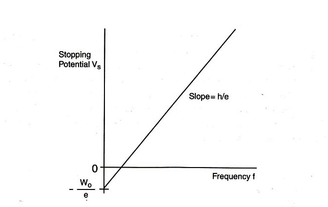
\begin{eqnarray} V_{\textrm{s}} &=& (h/e)f - W_0/e. \label{eqn_5} \end{eqnarray}
Eq. \eqref{eqn_5} shows a linear relationship between the stopping potential \(V_{\textrm{s}}\) and the light frequency \(f\), with slope \(h/e\) and vertical intercept \(-W_0/e\). If the value of the electron charge \(e\) is known, then this equation provides a good method for determining Planck's constant \(h\). In this experiment, we will measure the stopping potential with modern electronics.
THE PHOTODIODE AND ITS READOUT
The central element of the apparatus is the photodiode tube. The diode has a window which allows light to enter, and the cathode is a clean metal surface. To prevent the collision of electrons with air molecules, the diode tube is evacuated.
The photodiode and its associated electronics have a small “capacitance” and develop a voltage as they become charged by the emitted electrons. When the voltage across this “capacitor” reaches the stopping potential of the cathode, the voltage difference between the cathode and anode (which is equal to the stopping potential) stabilizes.
To measure the stopping potential, we use a very sensitive amplifier which has an input impedance larger than 10 13 ohms. The amplifier enables us to investigate the minuscule number of photoelectrons that are produced.
It would take considerable time to discharge the anode at the completion of a measurement by the usual high-leakage resistance of the circuit components, as the input impedance of the amplifier is very high. To speed up this process, a shorting switch is provided; it is labeled “Push to Zero”. The amplifier output will not stay at 0 volts very long after the switch is released. However, the anode output does stabilize once the photoelectrons charge it up.
There are two 9-volt batteries already installed in the photodiode housing. To check the batteries, you can use a voltmeter to measure the voltage between the output ground terminal and each battery test terminal. The battery test points are located on the side panel. You should replace the batteries if the voltage is less than 6 volts.
THE MONOCHROMATIC LIGHT BEAMS
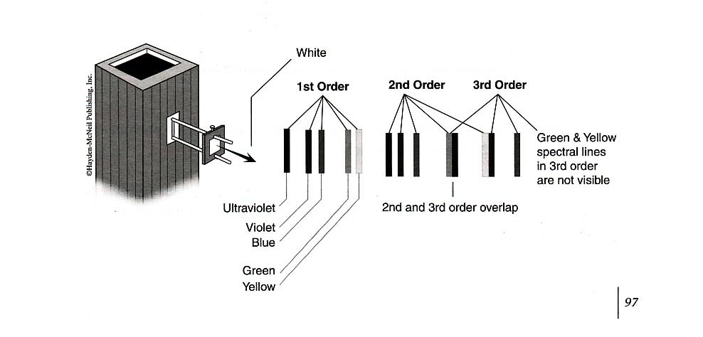
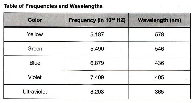
This experiment requires the use of several different monochromatic light beams, which can be obtained from the spectral lines that make up the radiation produced by excited mercury atoms. The light is formed by an electrical discharge in a thin glass tube containing mercury vapor, and harmful ultraviolet components are filtered out by the glass envelope. Mercury light has five narrow spectral lines in the visible region — yellow, green, blue, violet, and ultraviolet — which can be separated spatially by the process of diffraction. For this purpose, we use a high-quality diffraction grating with 6000 lines per centimeter. The desired wavelength is selected with the aid of a collimator, while the intensity can be varied with a set of neutral density filters. A color filter at the entrance of the photodiode is used to minimize room light.
The equipment consists of a mercury vapor light housed in a sturdy metal box, which also holds the transformer for the high voltage. The transformer is fed by a 115-volt power source from an ordinary wall outlet. In order to prevent the possibility of getting an electric shock from the high voltage, do not remove the cover from the unit when it is plugged in.
To facilitate mounting of the filters, the light box is equipped with rails on the front panel. The optical components include a fixed slit (called a light aperture) which is mounted over the output hole in the front cover of the light box. A lens focuses the aperture on the photodiode window. The diffraction grating is mounted on the same frame that holds the lens, which simplifies the setup somewhat. A “blazed” grating, which has a preferred orientation for maximal light transmission and is not fully symmetric, is used. Turn the grating around to verify that you have the optimal orientation.
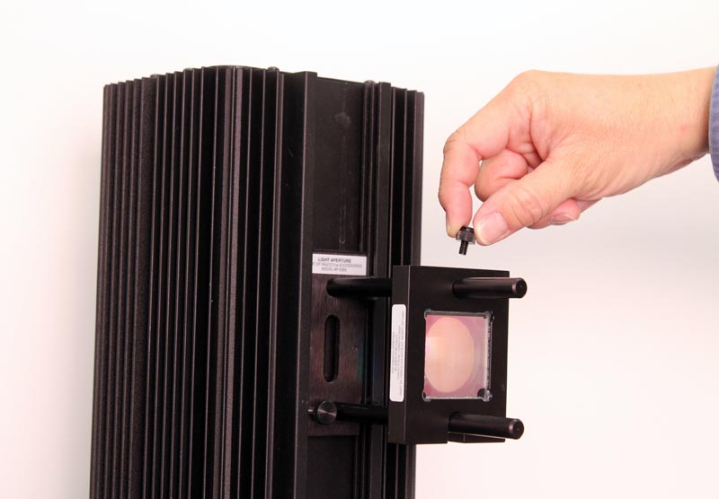
The variable transmission filter consists of computer-generated patterns of dots and lines that vary the intensity of the incident light. The relative transmission percentages are 100%, 80%, 60%, 40%, and 20%.
INITIAL SETUP
Your apparatus should be set up approximately like the figure above. Turn on the mercury lamp using the switch on the back of the light box. Swing the \(h/e\) apparatus box around on its arm, and you should see at various positions, yellow green, and several blue spectral lines on its front reflective mask. Notice that on one side of the imaginary “front-on” perpendicular line from the mercury lamp, the spectral lines are brighter than the similar lines from the other side. This is because the grating is “blazed”. In you experiments, use the first order spectrum on the side with the brighter lines.
Your apparatus should already be approximately aligned from previous experiments, but make the following alignment checks. Ask you TA for assistance if necessary.
Check the alignment of the mercury source and the aperture by looking at the light shining on the back of the grating. If necessary, adjust the back plate of the light-aperture assembly by loosening the two retaining screws and moving the plate to the left or right until the light shines directly on the center of the grating.
With the bright colored lines on the front reflective mask, adjust the lens/grating assembly on the mercury lamp light box until the lines are focused as sharply as possible.
Roll the round light shield (between the white screen and the photodiode housing) out of the way to view the photodiode window inside the housing. The phototube has a small square window for light to enter. When a spectral line is centered on the front mask, it should also be centered on this window. If not, rotate the housing until the image of the aperture is centered on the window, and fasten the housing. Return the round shield back into position to block stray light.
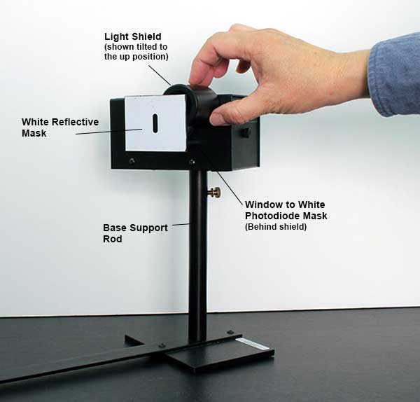
Connect the digital voltmeter (DVM) to the “Output” terminals of the photodiode. Select the 2 V or 20 V range on the meter.
Press the “Push to Zero” button on the side panel of the photodiode housing to short out any accumulated charge on the electronics. Note that the output will shift in the absence of light on the photodiode.
Record the photodiode output voltage on the DVM. This voltage is a direct measure of the stopping potential.
Use the green and yellow filters for the green and yellow mercury light. These filters block higher frequencies and eliminate ambient room light. In higher diffraction orders, they also block the ultraviolet light that falls on top of the yellow and green lines.
PROCEDURE PART 1: DEPENDENCE OF THE STOPPING POTENTIAL ON THE INTENSITY OF LIGHT
Adjust the angle of the photodiode-housing assembly so that the green line falls on the window of the photodiode.
Install the green filter and the round light shield.
Install the variable transmission filter on the collimator over the green filter such that the light passes through the section marked 100%. Record the photodiode output voltage reading on the DVM. Also determine the approximate recharge time after the discharge button has been pressed and released.
Repeat steps 1 – 3 for the other four transmission percentages, as well as for the ultraviolet light in second order.
Plot a graph of the stopping potential as a function of intensity.
PROCEDURE PART 2: DEPENDENCE OF THE STOPPING POTENTIAL ON THE FREQUENCY OF LIGHT
You can see five colors in the mercury light spectrum. The diffraction grating has two usable orders for deflection on one side of the center.
Adjust the photodiode-housing assembly so that only one color from the first-order diffraction pattern on one side of the center falls on the collimator.
For each color in the first order, record the photodiode output voltage reading on the DVM.
For each color in the second order, record the photodiode output voltage reading on the DVM.
Plot a graph of the stopping potential as a function of frequency, and determine the slope and the \(y\)-intercept of the graph. From this data, calculate \(W_0\) and \(h\). Compare this value of \(h\) with that provided in the “Introduction” section of this experiment.
Procedure Part 1:
Photodiode output voltage reading for 100% transmission =
Approximate recharge time for 100% transmission =
Photodiode output voltage reading for 80% transmission =
Approximate recharge time for 80% transmission =
Photodiode output voltage reading for 60% transmission =
Approximate recharge time for 60% transmission =
Photodiode output voltage reading for 40% transmission =
Approximate recharge time for 40% transmission =
Photodiode output voltage reading for 20% transmission =
Approximate recharge time for 20% transmission =
Photodiode output voltage reading for ultraviolet light =
Approximate recharge time for ultraviolet light =
Plot the graph of stopping potential as a function of intensity using one sheet of graph paper at the end of this workbook. Remember to label the axes and title the graph.
Procedure Part 2:
First-order diffraction pattern on one side of the center:
Photodiode output voltage reading for yellow light =
Photodiode output voltage reading for green light =
Photodiode output voltage reading for blue light =
Photodiode output voltage reading for violet light =
Second-order diffraction pattern on the other side of the center:
Plot the graph of stopping potential as a function of frequency using one sheet of graph paper at the end of this workbook. Remember to label the axes and title the graph.
Slope of graph =
\(y\)-intercept of graph =
\(W_0\) =
\(h\) =
Percentage difference between experimental and accepted values of \(h\) =

{:instructional:lab_manuals:physics:6c:experiment_7:photo_graph_2.jpg|}}


IMAGES
COMMENTS
When a 180-nm light is used in an experiment with an unknown metal, the measured photocurrent drops to zero at potential – 0.80 V. Determine the work function of the metal and its cut-off frequency for the photoelectric effect.
In various experiments on photo electricity, the stopping potential for a given frequency of the incident radiation is _____. When a beam of 10.6 eV photons of intensity 2.0 W/m 2 falls on a platinum surface of area 1.0 × 10 -4 m 2 , only 53% of the incident photons eject photoelectrons.
The stopping potential is applied to oppose the motion of the photoelectrons. At the stopping potential, the kinetic energy of the most energetic photoelectrons is converted into electrical potential energy: eVo = ½ mv₀². Combining equations 3 and 4, we get Einstein's photoelectric equation.
In the case of photoelectric effect experiment, explain the following facts, giving reasons. The photoelectric current increases with increase of intensity of incident light. Define the term: stopping potential in the photoelectric effect. Two monochromatic beams A and B of equal intensity I, hit a screen.
Therefore, the decrease in the stopping potential during the photoelectric experiment is 1V. 3. When ultraviolet light with a wavelength of 230 nm shines on a particular metal plate, electrons are emitted from plate 1, crossing the gap to plate 2 and causing a current to flow through the wire connecting the two plates.
When the voltage across this “capacitor” reaches the stopping potential of the cathode, the voltage difference between the cathode and anode (which is equal to the stopping potential) stabilizes. To measure the stopping potential, we use a very sensitive amplifier which has an input impedance larger than 10 13 ohms. The amplifier enables us ...
1. Photoelectric effect Background Photoelectric effect Planck’s constant Work function Photocell Aim of the experiment To determine the Planck’s quantum of action from the stopping potentials measured at different wavelengths, and to study the effect of the incident intensity on the photocurrent and the stopping potential at a fixed ...
Combining (1), (2) and (3), we obtain Einstein’s equation for the photoelectric effect: eVstop =hf −E0 (4) According to (4), the stopping potential is a linearly increasing function of f: ( f f0) e h Vstop = − (5) A graph of V stop vs. f would provide a way to measure Planck’s constant h and the cutoff (or threshold) frequency f 0 ...
Define photoelectric effect. State Einstein photoelectric equation. Explain 2 characteristics of the photoelectric effect on the basis of Einstein’s photoelectric equation. The maximum velocity of photoelectron emitted is 4.8 m/s. If the e/m ratio of the electron is 1.76 × 10 11 C/kg, then stopping potential is given by _____
stop). V. sto. p. is called the stopping potential and it is independent of the intensity of the irradiating light source but dependent on the frequency of the source. An electron with kinetic energy . E. k. ejected by the cathode will be prevented from reaching the anode by a stopping voltage . V. stop = E. k / e (2) Einstein’s interpretation